


Altair Cameras
Features
The driver supports the standard single-frame capture mode in addition to video streaming when supportted. Furthermore, it supports:
- Guiding via ST4 port.
- Color and Mono cameras.
- 8, 10, 12, 14 and 16 bit support. For 10, 12 and 14bit cameras, the images are always stored using 16bit depth.
- Temperature control if cooler is available.
- Black and White balance adjustments.
- USB Speed control: This is important when the camera is used on ARM architectures like the Raspberry PI3.
- Gain, Brightness, Saturating, Gamma...etc controls.
Operation
Connecting to Altair Cameras
Simply connect the camera via USB to your PC or SBC (Single board computer). The camera can be connected to an external powered hub as well. You can connect multiple cameras
The camera is very sensitive to power fluctuations. Make sure to use a 3A power supply if the camera is connected to StellarMate. The USB speed is automatically adjusted to lower values since USB bandwidth on RPI4 is limited and can cause the camera to indefnitely loop. If the camera gets stuck during exposure, change the cable, and check the power and USB speed settings.
General Info
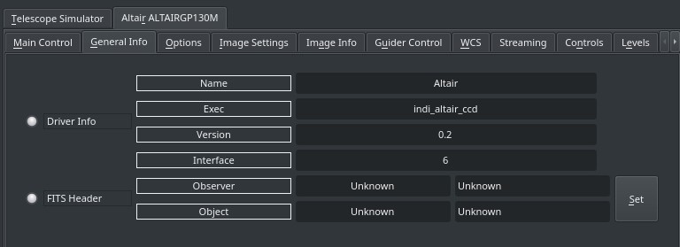
This provides general information about the currently running driver and driver version. It also lets you set the Observer and Object Information for the FITS Header.
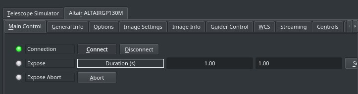
Capture
To capture a signle-frame image, simple set the desired exposure time in seconds and click Set. After the capture is complete, it should be downloaded as a FITS image. If the camera is equipped with a cooler, target temperature can be set. To change the format and bit depth (if supported), select a different image format in the Controls tab.
Options
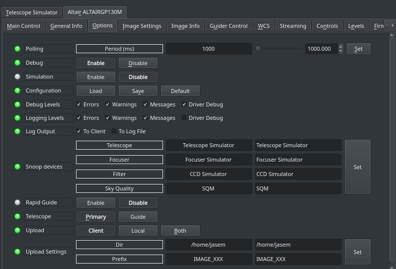
The Options tab contains settings for default file locations, upload behavior, and debugging. The polling period for this driver should be kept as is unless you need to reduce it for a specific reason.
- Debug: Toggle driver debug logging on/off
- Configuration: After changing driver settings, click Save to save the changes to the configuration file. The saved values should be used when starting the driver again in the future. The configuration file is saved to the user home directory under .indi directory in an XML file.(e.g. ~/.indi/camera_name.xml)
- Snoop Device: The camera driver can listen to properties defined in other drivers. This can be used to store the relevant information in the FITS header (like the mount's RA and DE coordinates). The respective drivers (Telescope, Focuser..etc) are usually set by the client, but can be set directly if desired.
- Rapid Guide: Rapid Guide uses internal algorithm to automataically select guide stars.
- Telescope: Toggle between Primary and Guide scope selection. This selection is required in order to calculate World-Coordinate-System (WCS) values like Field-Of-View (FOV). When WCS is enabled, the FITS header is populated with WCS keywords that enable clients to map the sources in the image to physical coordinates in the sky. Usually, you do not need to toggle this setting manually as it is usually set by the client automatically
- Upload: Selects how the captured image is saved/uploaded?
- Client: The image is uploaded the client (i.e. Ekos or SkyCharts)
- Local: The image is saved to local storage only.
- Both: The image is saved to local storage and also uploaded to the client.
- Upload Settings: Sets the local desired directory and prefix used to save the image when either the Local or Both upload modes are active. The IMAGE_XXX is automatically replaced by the image name where the XXX is the image counter (i.e. M42_005.fits). The driver scan the local storage and increments the counter automatically when a new image is captured and stored.
Image Settings
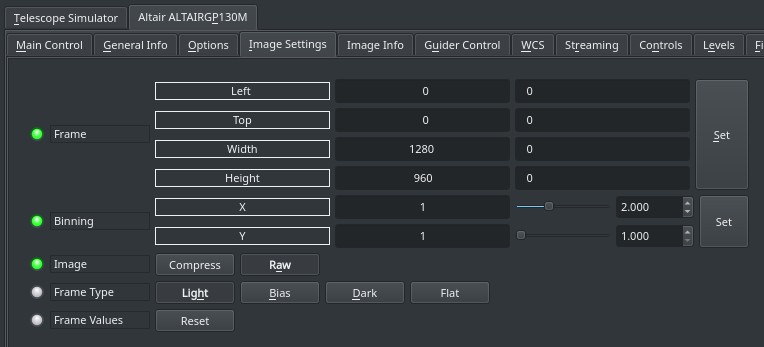
In the Image Settings tab, you can configure the framing and binning of the captured image:
- Frame: Set the desired Region-Of-Interest (ROI) by specifying the starting X and Y positions of the image and the desired width and height. It is recommended to set use even numbers only to enable binning if required. The ROI values are indenepdent of the binning used.
- Binning: Set the desired binning. The usually supported
Image compression can be turned on in image settings to compress FITS images. This might require more processing but can reduce the size of the image by up to 70%. The uploaded image would have an extenstion of .fits.fz and it can be viewed in multiple clients like KStars.
The Frame Type property is used to mark the frame type in the FITS header which is useful information for some processing applications. If there an electronic or mechanical shutter, the driver closes it automatically when taking dark frames.
To restore the ROI to the default values, click on the Reset button.
Image Info
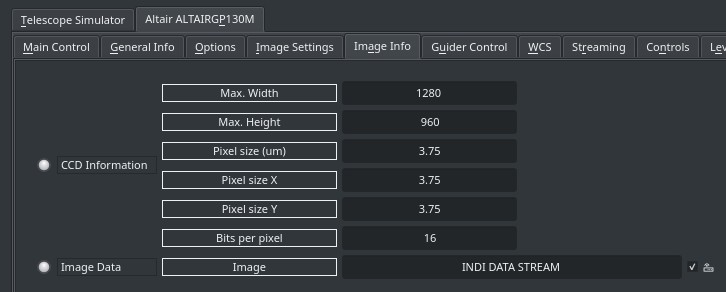
The image info tab contains information on the resolution of the CCD (Maximum Width & Height) in addition to the pixel size in microns. If the camera supports Bayer mask, then the bayer filter and offset can be set here. These are usually set automatically by the driver, but can be adjusted manually if needed.
Controls
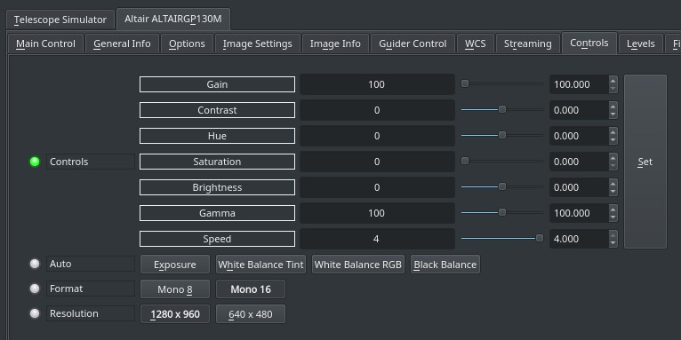
The controls tab provides settings to adjust common camera parameters such as gain, gamma, brightness, contrast..etc.
A very important parameter is the Speed setting. Setting it to maximum will fully utlize the USB bandwidth available on the device and will deliver images faster, but this is problematic on small embedded device like Raspberry PI. For such devices, the USB speed default to 0. You may expeiment with adjusting it until you achieve a good balance between performance and stability. Sometimes, even lower USB speed would not resolve image capture failures on embedded devices. Try selecting a lower resolution and then try again.
The Auto switches enable to automatically calibrate exposure and while/black balance using the camera own internal algorithms. For astronomy, it is usually recommended to set all controls manually to achieve the most level of control over the produced images.
Some cameras support higher bit depth rates such as 10, 12, and 14bits. However, the generated FITS file is either 8bit or 16bit, so any intermediate bit depths are automatically stored as 16bit.
For color camera, the formats are RGB and RAW. If RGB is selected, the FITS color image would be stored as an 8bit per channel color image. For RAW images, the FITS image is stored using higher bit depths if supported by the camera (10, 12..etc). Therefore, to capture images in high bit-depths, select the RAW format.
The image resolution can be directly selected here, though it is prefreable to set the ROI in the Image Settings tab.
Dual Gain
Modern CMOS sensor often support Dual Conversion Gain with a Low and High Conversion Gain setting (LCG/HCG). When the camera supports Dual Gain, three additional parameters are displayed at the Control Tab. High Conversion Gain (HCG) multiplies the gain with an additional factor. This has a positive impact on the read noise. The regular Gain parameter has a continuous range taking the conversion gain setting into account.
The HCG Threshold is the gain setting at which the camera switches over to HCG. For example with IMX294 sensors this is usually set to 900. The HCG/LCG gain ratio is a fixed property of the camera and needs to be set to the design value. For the IMX294 the value is 4.5. For other camera's it is usually 2.0. The Dual Gain Mode parameter enables the special HDR mode of the camera, as well as overriding the HCG/LCG setting.
Dual Gain can be disabled by setting HCG/LCG gain ratio to 1.0. Dual Gain is disabled when HDR is selected.
On embedded platforms (Raspberry Pi, Odroid..etc), the camera exposure can fail with Exposure Timeout messages due to limitations in the camera SDK as it does not properly handle USB bandwidth on embedded devices. As of 2020-02-18, the SDK is still not updated to fix the USB resolution issues. One way to resolve this issue is by reducing the resolution.
Levels
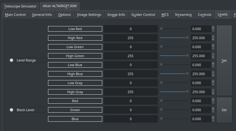
Control the maximum and minimum ranges for all color channels. The RGB black levels can also be adjusted. By default, all levels are set to the maximum data range (0-255).
Firmware
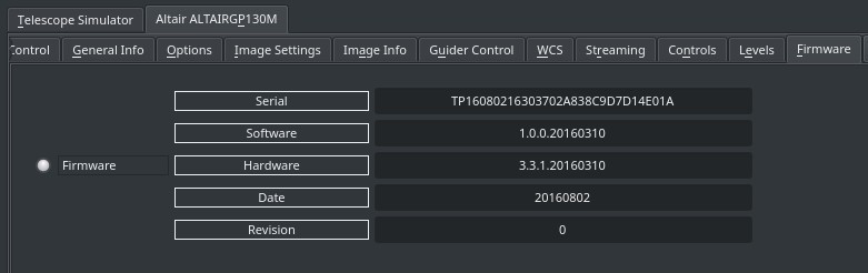
Display the camera firmware information.
Website
Driver Name
Altair
Driver Executable
indi_altair_ccd
Family
CCDs
Manufacturer
Altair Astro
Platforms
Linux, MacOS
Author
Jasem Mutlaq
Version
1.1