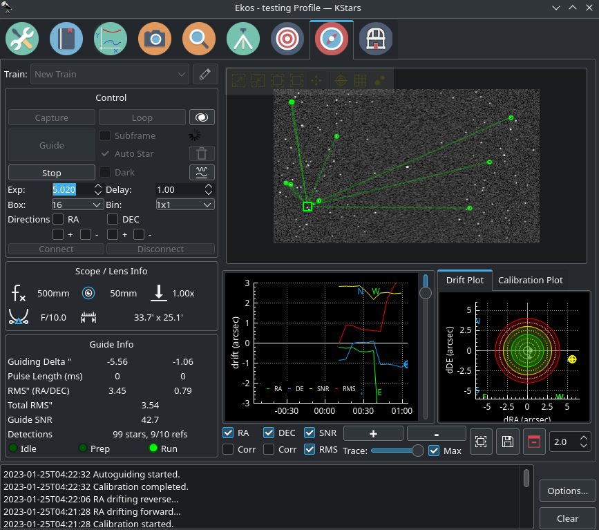
Introduction
Ekos Guide Module enables autoguiding capability using either the powerful built-in guider, or externally via PHD2. Using the internal guiding, guide camera frames are captured and sent to Ekos for analysis. Depending on the deviations of the guide star from its lock position, guiding pulses corrections are sent to your mount Via any device that supports ST4 ports. Alternatively, you may send the corrections to your mount directly, if supported by the mount driver. Most of the settings in the Guide Module include tooltips for additional context.
When creating your equipment profile for the first time, you need to designate the Optical Train used for guiding. Each camera in your equipment profile requires a separate optical train, even if both mounted on the same OTA (e.g. OAG).
It is important to set where the guide pulses are sent to in your guide train. This is sometimes overlooked and would cause guide calibration to fail. Make sure the guiding pulses are sent to the correct driver. Unless you are using an ST4 cable, the Guide Via option in your optical train should be set to the primary mount.
Autoguiding is a two-step process: Calibration & Guiding.
During the two processes, you may set the following:
- Exposure: camera exposure in seconds
- Stepper-geared mounts: No less than 2 seconds.
- Strain-wave mounts: No more than 1 second unless no stars are present.
- Delay: Wait many seconds after the last guiding pulse is sent before capturing the next frame. If your exposure time is super short (i.e. less than a second), then this might be useful as you do not want to send the guiding corrections at the same frequency.
- Binning: camera binning.
- Box: Size of the box enclosing the guide star. Select a suitable size that is neither too large nor too small for the selected star.
- Gain: Camera gain, if supported.
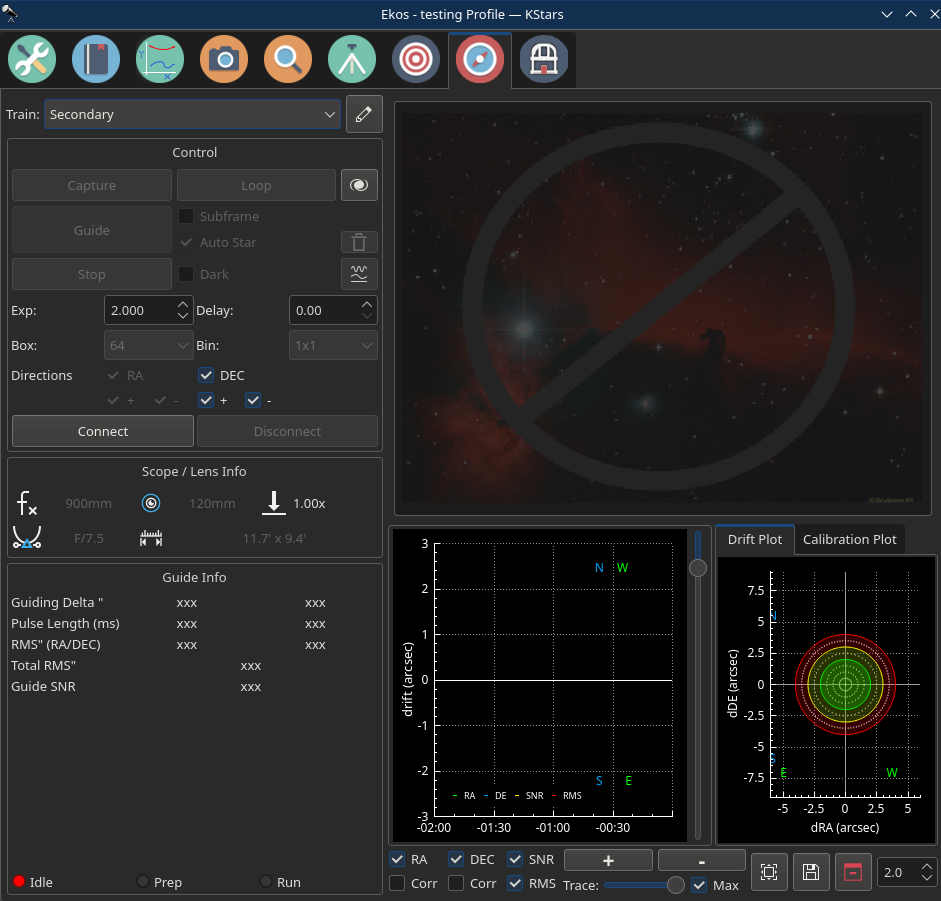
Main Module Controls
Most of the main module controls are briefly explained in this section.
Control
- Capture: Takes one capture
- Guide: Starts the guiding process
- Stop: Stops the guiding process
- Loop: Starts taking frames continuously.
- Subframe: Subframe the image around the guide star. For PHD2, receive the Guide Star Image instead of the full image frame. For the Internal Guider, before checking this option, you must first capture an image and select a guide star. Uncheck it to take a full frame again.
- Auto Star: Disabled in multi-guiding (default). For classical single-star guiding, you may opt to let the system pick the star or you can select it manually.
- Dark: Subtract dark frame. You must always have suitable dark frames in your Dark Library.
- Show in FITS Viewer: Shows frame in FITS Viewer
Pulses Controls
- Directions: Control which directions may receive the guiding corrections:
- RA: Guide Right Ascension Axis
- +: East Direction Guiding
- -: West Direction Guiding
- DEC: Guide Declination Axis
- +: North Direction Guiding
- -: South Direction Guiding
- Clear calibration data
 : Clears all the calibration data for the guiding process.
 - Manual Dither
 : Allows manual dithering.
 - Exp: Exposure time in seconds.
- Bin: Guide camera binning. It is recommended to set binning to 2x2 or higher.
- Gain: Specify the value of gain.
- Box: Guide star tracking box size. Box size must be set in accordance to the selected star size.
- Effects: Apply filter to image after capture to enhance it.
- Connect: Connect to external guiding application.
- Disconnect: Disconnect from external guiding application.
Manual Pulses
A simple tool to test how your mount axis responds to manual guide pulses. The mount must be tracked sidereally when using this tool. The RA and DE offsets in arc seconds track how far the mount moved since you opened the tool. You can reset the tracking at any time by clicking on the Reset button.
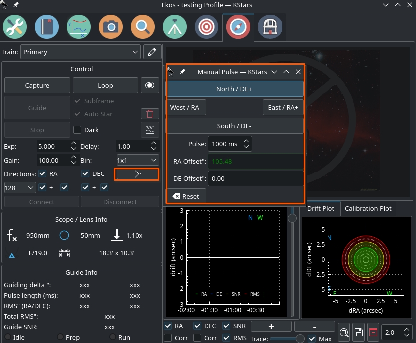
Click on any of the four directional buttons to see if your pulses have a corresponding change in the mount RA and DE axis. You should notice a slight change in the RA and DE offsets when using these controls. If the RA and DE offsets do not change, then this likely indicates a configuration, electrical, or mechanical issue with your mount. Please ensure that your mount is set as the Guide Via setting in your optical train unless you are using an ST4 cable or device.
Guide Info
- Focal length: Guide camera focal length. Unit is in millimeters (mm)
- Aperture: Guide camera aperture. Unit is in millimeters (mm)
- F/D: Focal ratio
- FOV: Field of view (arcmin)
- Guiding Delta ": Immediate Guiding RA deviation in arcseconds and Immediate Guiding DEC deviation in arcseconds respectively.
- Pulse Length (ms): Generated RA pulse and Generated DEC pulse respectively.
- RA RMS": RA Guiding RMS error.
- DE RMS": DEC Guiding RMS error.
- Total RMS": Total Guiding RMS error.
- Guide SNR: Guide Signal-to-noise ratio.
Calibration
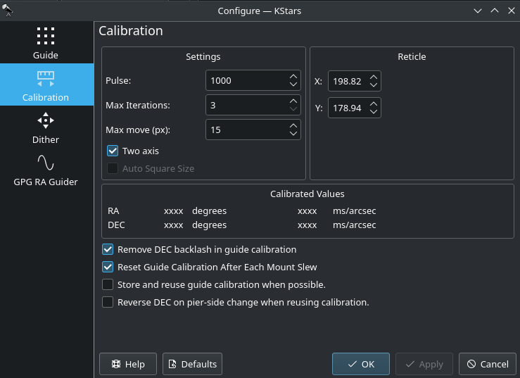 In the calibration phase, you need to capture an image, select a guide star, and click Guide to begin the calibration process. If calibration was already completed successfully before, then the auto guiding process shall begin immediately, otherwise, it would start the calibration process. If Auto Star is checked, then you are only required to click capture and Ekos will automatically select the best fit guide star in the image and continues the calibration process automatically. If Auto Calibration is disabled, Ekos will try to automatically highlight the best guide star in the field. You need to confirm or change the selection before you can start the calibration process. The calibration options are:
- Pulse: The duration of pulses in milliseconds to be sent to the mount. This value should be large enough to cause a noticable movement in the guide star. If you increase the value and you do not notice any motion of the guide star, then this suggests possible mount issues such as jamming or connection issues via the ST4 cable.
- Two axis: Check if you want the calibration process calibration in both RA & DEC. If unchecked, the calibration is only performed in RA.
- Auto Star: If checked, Ekos will attempt to select the best guide star in the frame and begins the calibration process automatically.
The reticle position is the guide star position selected by you (or by the auto selection) in the captured guider image. You should select a star that is not close to the edge. If the image is not clear, you may select different Effects to enhance it.
Ekos begins the calibration process by sending pulses to move the mount in RA and DEC. If the calibration process fails due to short drift, try increasing the pulse duration. To clear calibration, click the trash-bin icon next to the Guide button.
Calibration can fail for a variety of reasons. To improve chances of success, try the tips below.
- Better Polar Alignment: This is critical to the success of any astrophotography session. Perform a quick polar alignment with a polar scope (if available) or by using Ekos Polar Alignment procedure in the Align module.
- Set binning to 2x2: Binning improves SNR and is often very important to the success of the calibration and guiding procedures.
- Prefer use ST4 cable between guide-camera and mount over using mount pulse commands.
- Select different filter (e.g. High contrast) and see if that makes a difference to bring down the noise.
- Smaller Square Size.
- Take dark frames to reduce noise.
- Play with DEC Proportional Gain or disable DEC control completely and see the difference.
- Leave algorithm to default value (Smart)
Guiding
 Once the calibration process is completed successfully, the guiding shall beging automatically hereafter. The guiding performance is displayed in the Drift Graphics region where Green reflects deviations in RA and Blue deviations in DEC. The colors of the RA/DE lines can be changed in KStars color scheme in KStars settings dialog. The vertical axis denotes the deviation in arcsecs from the guide star central position and the horizontal axis denotes time. You can hover over the line to get the exact deviation at this particular point in time. Furthermore, you can also zoom and drag/pan the graph to inspect a specific region of the graph.
Ekos can utilize multiple algorithms to determine the center of mass of the guide star. By default, the smart algorithm is suited best for most situation. The fast algorithm is based on HFR calculations. You can try switching guiding algorithms if Ekos cannot keep of the guide star within the guiding square properly.
The info region displays information on the telescope & FOV, in addition to the deviations from the guide star along with the correction pulses sent to the mount. The RMS value for each axis is displayed along with the total RMS value in arcsecs. The internal guider employs PID controller to correct the mount tracking. Currently, the only the propotional and integral gains are utilized within the algorithm, so adjusting it should affect the length of the generated pulses sent to the mount in milliseconds.
To enable automatic dithering between frames, make sure to check the Dither checkbox. By default, Ekos should dither (i.e. move) the guiding box after each frame captured in Ekos Capture Module. The motion duration and direction are randomized. Ekos will estimate the RA and DEC pulses necessary to move to the randomly generated position, and issue those pulses. Since the guiding performance can oscillate immediately after dithering, you can set the appropriate Settle duration to wait after dither is complete before resuming the capture process. In rare cases where the dithering process can get stuck in an endless loop, set the appropriate Timeout to abort the process. But even if dithering fails, you can select whether this failure should terminate the autoguiding process or not. Toggle Dither Failure Aborts Autoguide to select the desired behavior.
Note: Dithering will not obey the guider's axis and direction restrictions. For instance, if one chooses to only guide in RA, dithering will occur in both RA and DEC.
Non-guide dithering is also supported. This is useful when no guide camera is available or when performing short exposures. In this case, the mount can be commanded to dither in a random direction for up to the pulse specified in the Non-Guide Dither Pulse option.
Ekos supports multiple guiding methods: Internal, PHD2, and LinGuider. You need to select the desired guider in your Ekos equipment profile:
- Internal Guider: Use Ekos internal guider. This is the default and recommened option.
- PHD2: Use PHD2 as the external guider. If selected, specify the host and port of the PHD2. Leave to default values if Ekos and PHD2 are running on the same machine.
- LinGuider: Use LinGuider as the external guider. If selected, specify the host and port of the LinGuider. Leave to default values if Ekos and LinGuider are running on the same machine.

GPG RA Guider
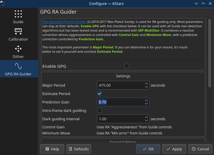 Ekos also supports GPG RA Guider, but this is for RA only--that is, guiding for DEC still happens, but using the existing guiding algorithms. This guider can be enabled by going to the Guide Module, clicking on Options (bottom-right) and then clicking on the GPG RA Guider tab and then checking the Enable GPG checkbox. This guider is based on the work in this PhD thesis and is the same as the well-regarded PHD2 guide algorithm known as Predictive PEC. It estimates the periodic error in the guiding system and tries to fix it before it happens. This system should perform about the same as the standard guider for the first period or two of your mount's periodic error, then improve. When using this system, it's best to set in advance what your mount's worm-gear period is. For example, the Orion Atlas pro is about 480s. You enable this in the Guide options menu, in the GPG RA tab, and then checking "Enable GPG". There are other parameters you can change, but as indicated earlier, the main one to think about is "Major Period".
It can be used with all Guide star-detection algorithms but has been tested most and is recommended with SEP MultiStar. It combines a reactive correction whose aggressiveness is controlled with Control Gain and Minimum Move, with a predictive correction controlled by Prediction Gain. Again, The most important parameter is Major Period. If you can determine it for your mount, it's much
better to set it yourself and uncheck Estimate Period.
Control Theory
PID guider. Stands for Proportional, Integral, Derivative control.
- Proportional means make corrections based on the error (e.g. you're off by 1 pixel in one direction, put the mount a certain amount in the other direction, and that amount is "control" times the error).
- Integral means look at the recent history of error (e.g. the average error in the past N samples) and make adjustments based on that. KStars defaults to not using that (e.g. the integral gain is 0).
- Derivative isn't implemented in KStars. (It looks at the rate that the system is approaching the target, preventing an overshoot)
If you're using GPG, the above 2 (Proportional & Integral) aren't used for RA, but rather the GPG settings.
Whether or not you're using GPG, DEC is controlled by Proportional and Integral.
Settings
- Enable GPG: Toggles GPG RA Guiding.
- Major Period: The length in seconds of the mount's major period that's being corrected. (look it up for your mount, and then uncheck estimate period, or alternatively if you're adventurous, run it with estimate period checked for an hour or two, and assuming you like the RA guiding during the last half of the interval, keep the period value it found and uncheck estimate period)
- Estimate Period: If checked, the GPG estimates the mount's major period. Otherwise, it uses the entry above.
- Prediction Gain: The fraction of its prediction the GPG uses to move the mount. Similar to Control Gain, but instead of error, now it has started making predictions of how to fix the error (based on the error and based on its periodic error estimate).
- Control Gain: The fraction of the guide-star drift that the GPG uses to move the mount. The GPG guider at the start uses a simple control mechanism (the pulse tries to correct the error). Control gain of 0.5 means "try to fix half of the error". Setting it 1.0 would likely result in an overcorrected system with poor guiding, so 0.5 is pretty normal.
- Minimum Move: The min-move parameter the GPG uses to move the mount when it uses its backoff proportional guider. (don't react to errors less that XXX--but really min move is in units of pulse ms, so don't put out a shorter correction pulse than XXX) and Max (don't put out a pulse greater than XXX.)
You can make the GPG guiding less aggressive by reducing control gain. If you want the guiding process to be less aggressive, make the guide exposure pretty long (e.g. 3 or 4 or 5s), reduce the control gain, reduce the prediction gain, and increase the min move. If you suspect that you don't have much periodic error you should consider NOT using GPG.
If you have no idea what to set Control and Prediction gains, keep them around their defaults (in the 0.5 area).
Expert Settings
- Long-range Length Scale: Length scale of the long range kernel.
- Long-range Variance: Long-range kernel signal variance
- Periodic Length Scale: Periodic Kernel length scale
- Periodic Variance: Periodic kernel signal variance
- Short-range Length Scale: Length scale of the short-range kernel
- Short-range Variance: Short-range kernel signal variance
- Approximation Points: Number of points used in the Gaussian Process approximation
- Num Periods for Inference: The min number of periods that must be sampled before prediction is fully used. Before that, it is mixed with the control/proportional guider.
- Num Periods for Period Estimate: The min number of periods that must be sampled before GPG fully estimates the period.
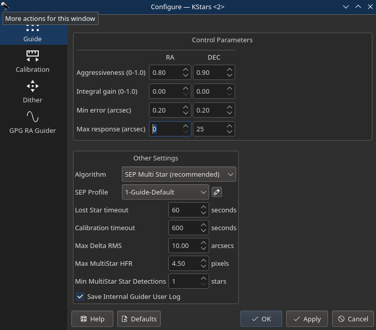
Guiding Direction Control
You can fine tune the guiding performance in the Control Section. The autoguide process works like a PID controller when sending correction commands to the mount. You can alter the Proportional and Integral gains to improve the guiding performance if necessary. By default, guiding corrective pulses are sent to both mount axis in all directions: positive and negative. You can fine-tune control by selecting which axis shall receive corrective guiding pulses and within each axis, you can indicate which direction (Positive) + or Negative (-) receives the guiding pulses. For example, for Declination axis, the + direction is North and - is South.
Guiding Rate
Each mount has a particular guiding rate in (x15"/sec) and usually ranges from 0.1x, to 1.0x with 0.5x being a common value used by many mounts. The default guiding rate is 0.5x sidereal, which is equivalent to a proportional gain of 133.33. Therefore, set the guiding rate value to whatever value used by your mount, and Ekos shall display the recommended propotional gain value that you may set in the propotationl gain field under the Control Parameters. Setting this value does not change your mount guiding rate! You must change your mount guiding rate either via the INDI driver, if supported, or via the hand controller.
Drift Graphics
 The drift graphics is a very useful tool to monitor the guiding performance. It is a 2D plot of guiding deviations and corrections. By default, only the guiding deviations in RA and DE are displayed. The horizontal axis is the time in seconds since the autoguiding process was started while the vertical axis plots the guiding drift/deviation in arcsecs for each axis. Guiding corrections (pulses) can also be plotted in the same graph and you can enable them by checking the Corr checkbox below each Axis. The corrections are plotted as shaded areas in the background with the same color as that of the axis.
You can pan and zoom the plot, and when hovering the mouse over the graph, a tooltip is displayed containing information about this specific point in time. It contains the guiding drift and any corrections made, in addition to the local time this even was recorded. A vertical slider to the right of the image can be used to adjust the height of the secondary Y-axis for pulses corrections.
The Trace horizontal slider at the bottom can be used to scroll through the guide history. Alternatively, you can click the Max checkbox to lock the graph onto the latest point so that the drift graphics autoscrolls. The buttons to the right of the slider are used for autoscaling the graphs, exporting the guide data to a CSV file, clearing all the guide data, and for scaling the target in the Drift Plot. Furthermore, the guide graph includes a label to indicate when a dither occurred so the user knows guiding was not bad at those points.
The colors of each axis can be customized in KStars Settings color scheme.
Drift Plot
A bulls-eye scatter plot can be used to gauge the accuracy of the overall guiding performance. It is composed of three concentric rings of varying radiuses with the central green ring having a default radius of 2 arcsecs. The last RMS value is plotted as ![]() with its color reflecting which concentric ring it falls within. You can change the radius of the inner most green circle by adjusting the drift plot accuracy.
with its color reflecting which concentric ring it falls within. You can change the radius of the inner most green circle by adjusting the drift plot accuracy.
Calibration Plot
The Calibration Plot shows the mount positions recorded during internal-guider calibration.
Basically, if things are going well, it should display dots in two lines which are at right angles to each other--one when the calibration pushes the mount back and forth along the RA direction, and then when it does the same for the DEC direction. Not a ton of info, but can be useful to see. If the two lines are at a 30-degree angle, something's not going well with your calibration! Here's a picture of it in action using the simulator.
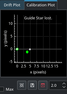
The colored dots (same color scheme as the internal guider) shows the RA and DEC samples on their way out, and the small white and yellow circles show their return paths.
Manual Dither
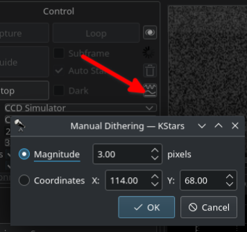
After guiding is started, it is possible to adjust the star lock position by clicking the Manual Dither button. The dialog provides two options:
- Magnitude: Specify the magnitude of the required manual dither in Pixels. This would move the lock position in a random direction by the specified magnitude.
- Coordinates: Specify the exact X,Y coordinates where the lock position should end up at. If the desired lock position is far away (> 3 pixels), it is recommend to move there is small steps. The initial coordinates position are that of the currently locked star.
For Spectroscopy applications, use the Coordinates option to adjust the star so that the target star light falls onto the reflective slit of the spectrograph
Guiding while Cloudy
It is possible to Guide in Ekos while it is partly cloudy. When the camera passes through a layer of clouds, guiding would be aborted followed shortly by the capture sequence. KStars developer Wolfgang Ressenberger suggested a few recommendations when guiding on partly cloudy night:
It does not matter how clouded the sky is as long as the small fraction of the sky you are capturing is clear. So the best approximation that capturing does not make sense is when guiding runs into problems with the guiding star. If there are clouds that are so heavy that guiding get's into trouble, the captured frame is worthless.
Reaction
If a guiding problem is detected, the best reaction is to immediately abort capturing. You can control this with the following parameters:
- Guiding options | Guide | Lost star timeout
If the guiding star is lost for this period of time, guiding aborts and subsequently capturing aborts. A typical value is 20 seconds. - Capture | Guide Limits | Abort if Guiding DeviationIt might happen that the guide star re-appears, but your scope is already to far off so that continuing would create elongated stars
Recovery
If you are using the Capture module standalone without the Scheduler, capturing will recover as soon as the guiding deviation is below the configured value. If this is unchecked, capturing will remain aborted.A more robust way for recovery is using the Scheduler. Its main feature is the "Aborted Job Management" that gives you the opportunity to try to restart capturing. There are two options that should be used, depending on the expected scenario:
- Aborted Job Management | Immediate
This is the option that I prefer. If a job aborts due to guiding problems and restarting guiding fails for 5 times, the Scheduler sets the job state to ABORTED and will retry to start it after the configured amount of time. This will happen as long as the constraints of the job remain valid. - Aborted Job Management | Queue
Similar to 1., but the Scheduler will jump to the next scheduled job and tries to start this one. This variant makes sense if you expect that the clouds remain in a certain part of the sky and starting the other job increases the chances to find some clear sky. From my experience, that does not happen very often and it's better to stay a a certain target.
Troubleshooting
Introduction
The Ekos Guide Module troubleshooting guide helps users diagnose and resolve common guiding issues. Before proceeding with troubleshooting, ensure your equipment profile and optical train configurations are properly set up. Each troubleshooting step includes specific actions to verify proper operation of the guiding system.
Equipment Configuration
Optical Train Setup
The Guide Via setting in your optical train must be configured correctly for guiding to function:
- Set to your mount if using direct guiding
- Set to your guide camera if using ST4 cable
- Incorrect Guide Via setting will cause calibration failures
Mount Configuration
Your mount must be:
- Properly balanced in both RA and DEC axes
- Tracking at sidereal rate
- Connected and responsive in INDI control panel
- Set to appropriate guide rates (typically 0.5x sidereal)
Manual Pulse Testing
A critical troubleshooting step is verifying mount response using manual pulses. The mount must be tracking sidereally when using this tool.
Expected Behavior
When using manual pulse controls:
- East pulse: RA coordinates should increase
- West pulse: RA coordinates should decrease
- North pulse: DEC coordinates should change
- South pulse: DEC coordinates should change in opposite direction
No Response to Pulses
If RA and DEC coordinates do not change when sending pulses:
- Verify Guide Via setting in optical train configuration
- Check guide port connections if using ST4
- Verify mount responds to movement commands in INDI control panel
- Check guide rates in mount configuration
Polar Alignment
Proper polar alignment is crucial for achieving good guiding performance. It is strongly recommended to use the Ekos Polar Alignment tool before starting any guiding session.
GPG Guider
The Ekos GPG (Gaussian Process Guider) is an advanced guiding algorithm that can improve guiding performance:
- Uses machine learning to predict and correct for periodic error
- Can handle multiple guide stars simultaneously
- More resistant to seeing conditions and temporary star loss
- Recommended for improved guiding stability
Guide Camera Setup
Frame Settings
- Exposure:
- Stepper-geared mounts: minimum 2 seconds
- Strain-wave mounts: maximum 1 second unless no stars visible
- Binning: 2x2 or higher recommended
- Box size: Must match selected star size
- Gain: Adjust based on star brightness and camera capabilities
Star Detection Issues
If unable to detect suitable guide stars:
- Increase exposure time
- Verify focus
- Check star detection threshold
- Ensure Dark Library frames are appropriate if using dark subtraction
Calibration Problems
Failed Calibration
Common causes:
- Incorrect Guide Via setting in optical train
- Mount not tracking
- Guide rates set too low
- Insufficient star SNR
- Cables binding or restricting movement
Poor Calibration Results
Check for:
- Mount alignment accuracy
- Mechanical issues
- Cable management
- Star saturation
- Appropriate pulse duration
- Mount firmware, is it up to date?
- Camera response time. Sometimes camera may delay sending frames or lock up. Ensure the camera is sending images back without any significant delays or artifacts.
- Noisy image: Use dark library to adjust for hot/cold pixels or dark frames to mitigate the thermal and sky noise in the image.
Guiding Performance
High RMS Errors
Verify:
- Polar alignment
- Mount periodic error: Check if there is a jump in RA in line with mount periodic error.
- Seeing conditions
- Wind: Is it too windy to guide properly?
- Guide parameters appropriate for mount
- Cable management not causing binding
Oscillations
Adjust:
- Decrease aggressiveness
- Increase minimum move time
- Check guide rates
- Verify no mechanical binding
PHD2 Support
You can opt to select external PHD2 application to perform guiding instead of the built-in guider.
If PHD2 is selected, the Connect and Disconnect buttons are enabled to allow you to establish connection with the PHD2 server. You can control PHD2 exposure and DEC guide settings. When clicking Guide, PHD2 should perform all the required actions to start the guiding process. PHD2 must be started and configured before Ekos.
After launching PHD2, select your INDI equipment and set their options. From Ekos, connect to PHD2 by clicking Connect button. On startup, Ekos will attempt to automatically connect to PHD2. Once connection is established, you may begin the guiding immediately by click on the Guide button. PHD2 shall perform calibration if necessary. If dithering is selected, PHD2 shall be commanded to dither given the offset pixels indicated and once guiding is settled and stable, the capture process in Ekos shall resume.
Ekos saves a CSV guide log data that can be useful for analysis of the mount's performance under ~/.local/share/kstars/guide_log.txt. This log is only available when using the built-in guider.