5. StellarMate App
StellarMate Mobile App for Tablets.
PC/Mac using KStars.
Any Web browser or VNC client.
StellarMate App is the Official App for StellarMate gadget. It is available for both Android and iOS smartphones and tablets. It is primary designed for tablets in portrait mode. While it can be used for phones, for the best experience, use it with a tablet/iPad. Download and install the App on your device before you continue.

|

|
Warning
The App is required to connect to the unit and configure it for first-time use, so do this step now and do not skip ahead!
5.1. Startup
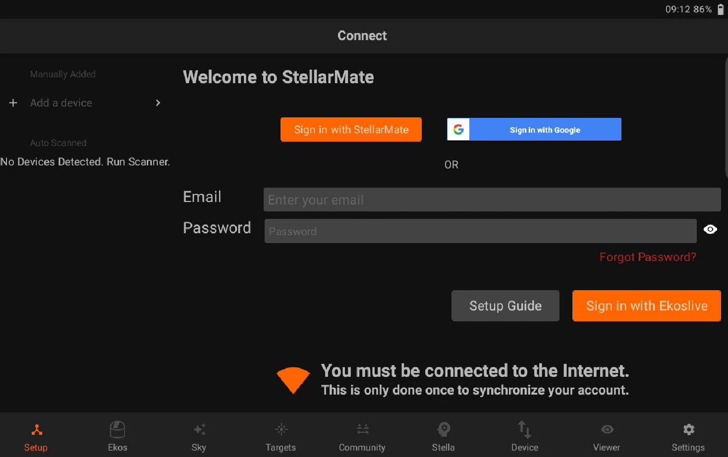
When using StellarMate App for the first time, you need to sign-in either using with Ekoslive, StellarMate or Google/Login account. Beware that you must be connected to the internet for the initial sign in to proceed. After sign in is successful, no internet connection is required and you can switch network to StellarMate hotspot if desired.
You can sign-in with your Google account in android and Sign-in with your Apple account on iOS devices
StellarMate X: If you purchased an SM X or SM Pro device, you need to register the device after Signing in. Press on the Register button and then follow the on screen guide.
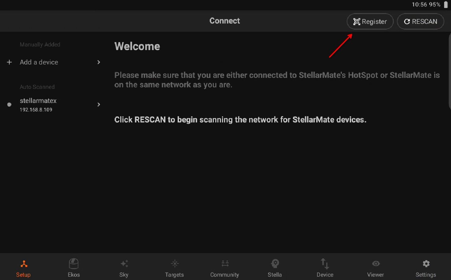
StellarMate OS: If you purchased StellarMate OS, or already have registered the device before, you can simply rescan and connect to your StellarMate device.
Register via:
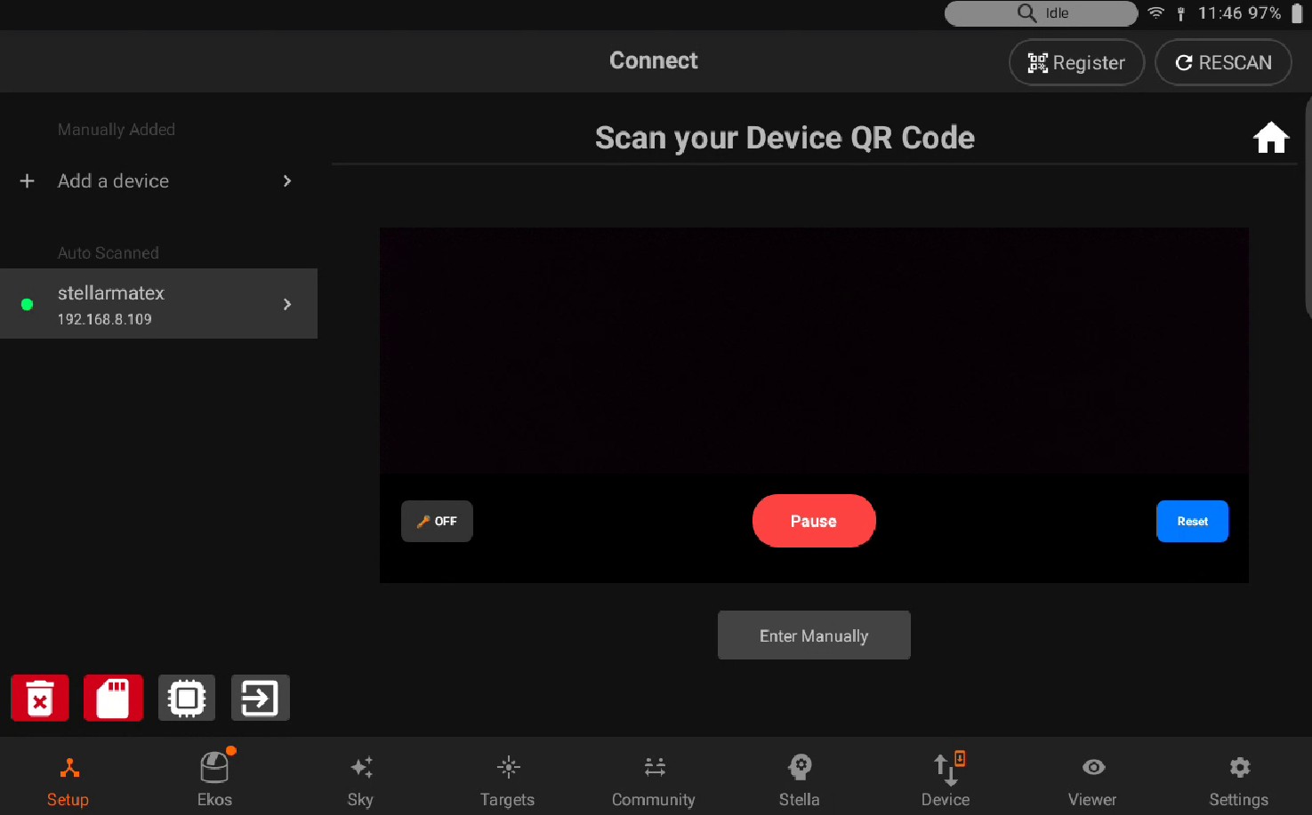
Scan QR code
Enter Manually
5.1.1. QR Code
If you received the StellarMate Controller, you will find the Device QR Code on the back of the unit.
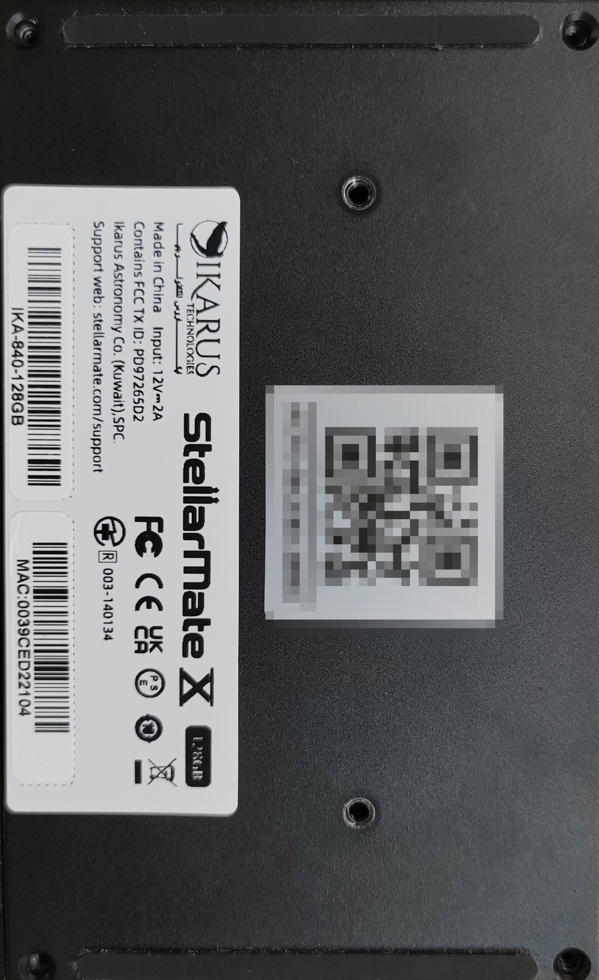
If you purchased StellarMate OS, the Device Serial Number is automatically generated for you.
5.1.2. Manually
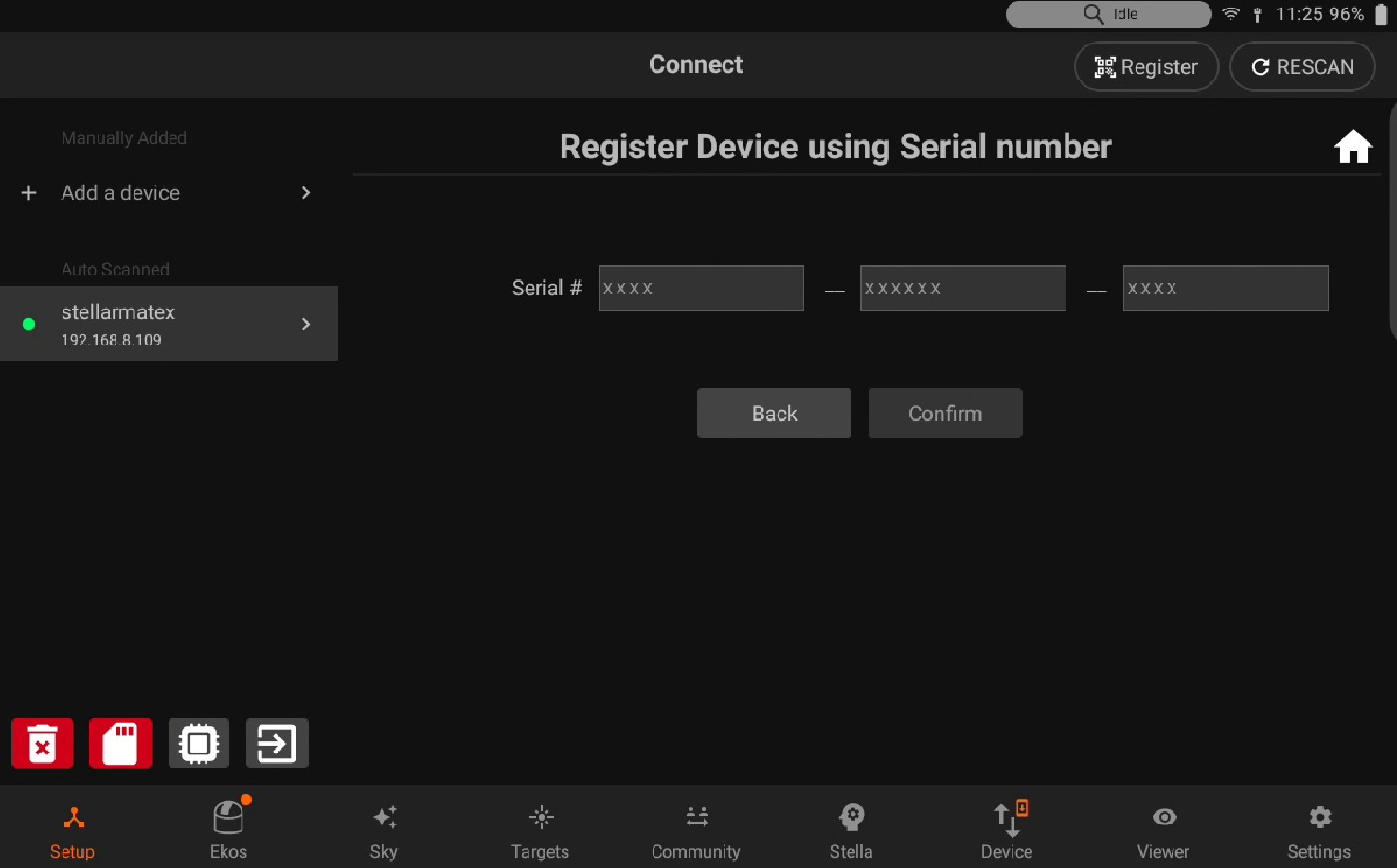
Enter the serial number located on the back of your StellarMate device. Once the correct serial number has been entered and pressed submit, it will be successfully registered to your account. Ensure that your device is connected to the Internet before proceeding.
5.1.3. Steps
Register your controller after downloading the SM App. Make sure your tablet is connected to the internet.
Launch StellarMate App on iOS or Android.
Sign-in to your account
Press Register button on the top right
Scan the QR Code found at the back of the unit.
Upon successful registration, the serial key will be linked to your email address.
Software vs Hardware licenses Software licenses are obtained through the purchase of StellarMate OS, whereas Hardware licenses are obtained through the purchase of StellarMate Hardware devices (e.g., SM X, SM Pro). Software licenses are activated automatically. Hardware licenses, however, must be activated manually using the StellarMate App’s registration feature, as described above.
Why do I get No License Information Found?
Starting with StellarMate App v3.0, StellarMate switched to a different management server for license data. If stale license data is encountered, you might receive this error.
The data can only be refreshed after signing in again to the App. Therefore, there are two approaches:
Go to Settings –> Logout and close the App and sign in again to refresh the data.
Completely uninstall and reinstall the App to ensure there is no residual cache left that might affect this issue.
5.2. Setup
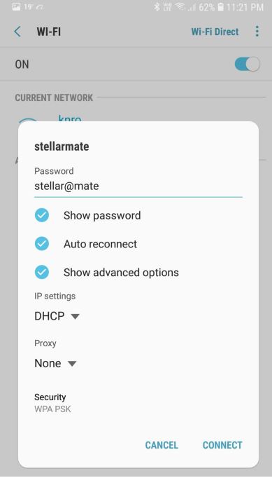
Go to your mobile OS WiFi settings and connect to the StellarMate hotspot. - Hotspot: stellarmate - Password: stellar@mate
Note
Before using the StellarMate App to configure your unit for the first time, please use the networking settings in your iOS/Android phone/tablet to connect to the HotSpot first. Once connected, proceed to run the StellarMate App.
After connecting to StellarMate, go back to the App:
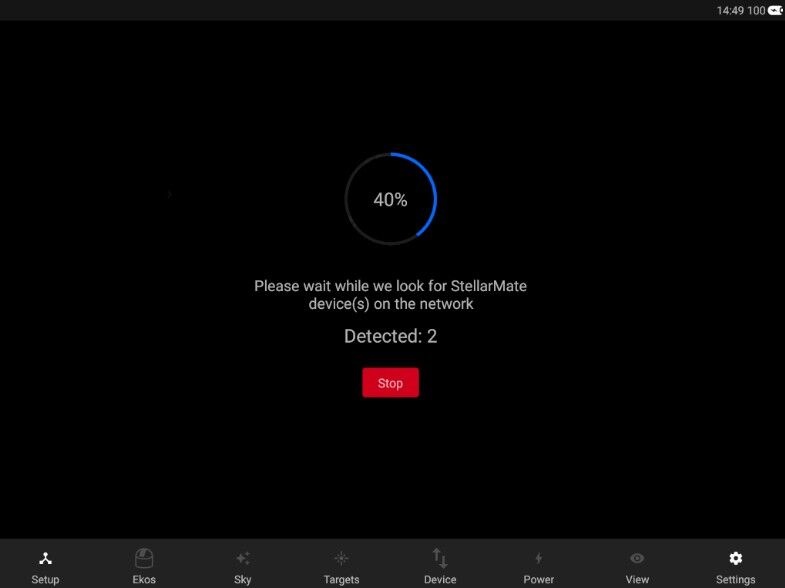
Tap on RESCAN to start the scanning process. Discovered devices would be listed on the left side pane.
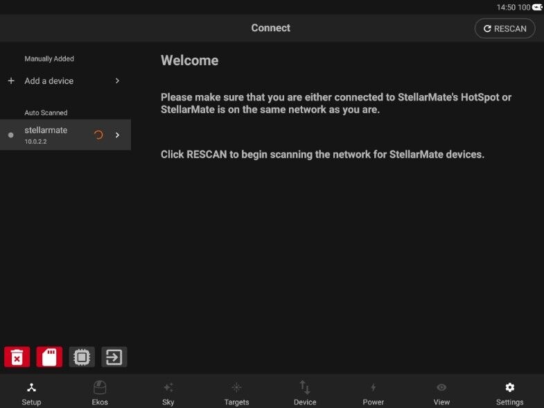
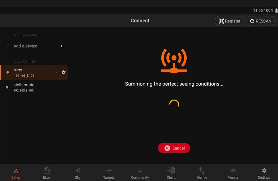
After StellarMate is detected, tap on it to establish connection. Wait for a few seconds and the LED would turn green indicating a stable successful connection.
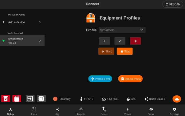
The right side pane should now display the Equipment Profile page. Now you are ready to connect to your astronomical equipment.
5.2.1. Connecting your devices
Most astronomical equipment such as telescopes, cameras, filter wheels, and focusers connect via a USB cable. To add your devices, you need to create a new Equipment Profile. Tap on the Add (+) icon next to the profiles to start the equipment profile wizard.
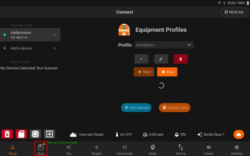
Once you start the Ekos profile and if it gets successfully connected you will see small LED Icon on the top of Ekos tab. This means you Ekos profile is running.
5.2.2. Advanced Settings
When creating a new equipment profile, you can adjust advanced settings including remote drivers and guider settings. Furthermore, advanced users can even start the profile in remote mode using StellarMate Web Manager.
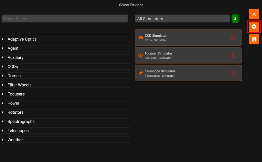
Note
The information below is intended for advanced users. If you are new to StellarMate, you can skip this section — the default settings work perfectly for most setups.
Driver Source By default, the Driver Source is set to System INDI Drivers. This means that the INDI drivers will continue to run, even if any service goes down, until the StellarMate device is powered off.
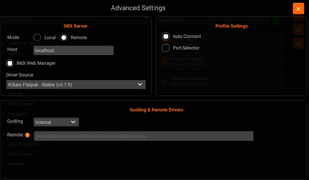
Understanding Flatpak vs System Drivers KStars is installed on StellarMate as a Flatpak application. This means KStars runs in an isolated container environment, separate from the rest of the system — including all INDI drivers. This isolation provides several benefits:
Consistency: KStars and its dependencies are bundled together, ensuring the same behavior regardless of the underlying system configuration.
Security: The Flatpak container is sandboxed from the rest of the system.
Easy Updates: Flatpak allows you to switch between different versions of KStars easily.
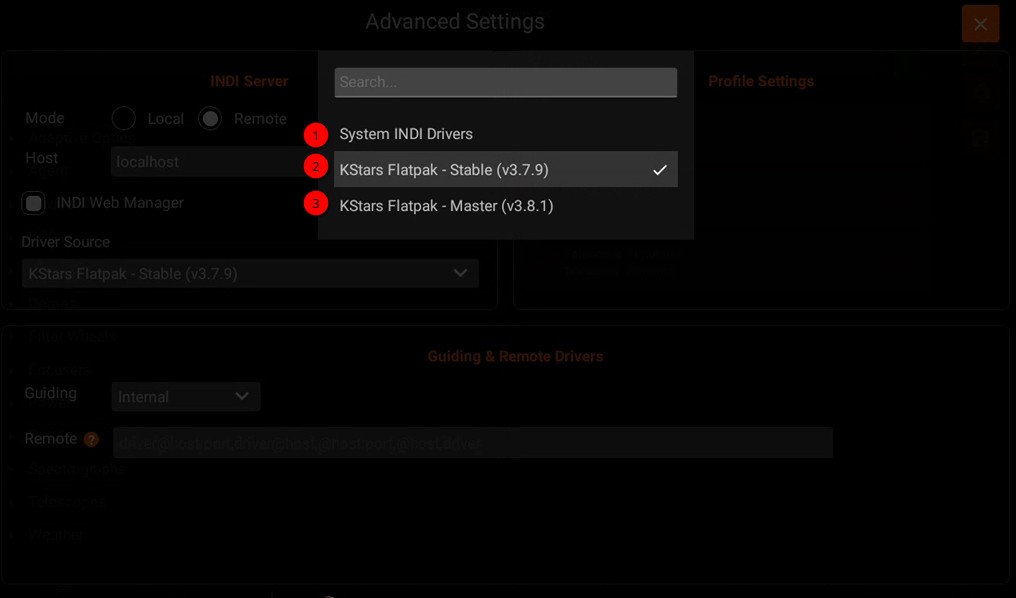
However, this also means that by default, the INDI drivers available inside the Flatpak container are limited to what is bundled with it. The Driver Source setting lets you choose which set of drivers KStars will use:
System INDI Drivers (default): Uses the INDI drivers installed directly on the StellarMate system, outside the Flatpak container. These drivers continue running even if KStars restarts or crashes.
Flatpak INDI Drivers: Uses the INDI drivers bundled inside the KStars Flatpak container. These drivers are tied to the lifecycle of the KStars application.
5.2.3. Port Selector
Your equipment profile may contain one or more serial port and/or network-enabled devices. Before establishing connection to such devices for the first time, StellarMate Port Selector tool helps you to assign the appropriate ports and addresses for each. Serial devices may include mounts, focuser, and filter wheels using USB-to-Serial adapters. You need to know the baud rate for the device as by default it is set to 9600.
Warning
PORT SELECTOR IS NOT APPLICABLE TO PURE USB DEVICES SUCH AS CAMERAS.
For networked devices over Ethernet or WiFi, you need to supply the device host name or IP address and the device port. This information is usually supplied by your device manufacturer. It is important to ensure that all networked devices are within the same network as StellarMate. For example, if StellarMate is operating in hotspot mode (IP 10.250.250.1) then your network-enabled device must be connected to the same hotspot network and have an IP address in this range (e.g. 10.250.250.5). On the other hand, when StellarMate is operating in infrastructure mode (i.e. it is connected to an external WiFi network like Home WiFi), then the other network-enabled devices must be connected to the same network in order for all devices to talk to each other. The Port Selector dialog can be accessed as any time by click on the Port Selector button. When creating an equipment profile for the first time, it is automatically opened so you can configure the ports before establishing connection to your devices either individually or via clicking Connect All buton.
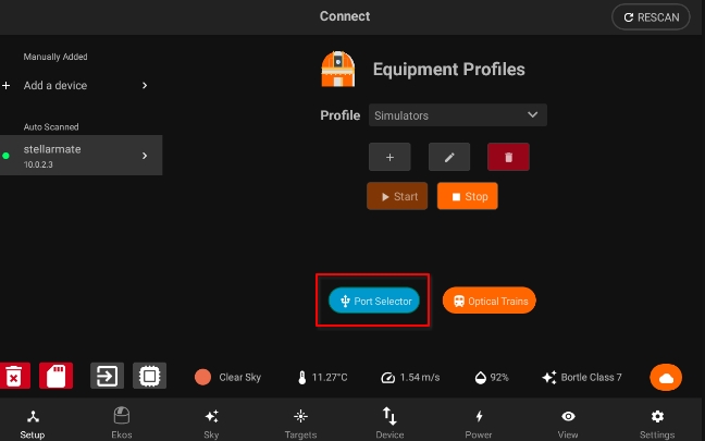
You can specify the ports for serial and network devices using the Port Selector.
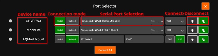
The serial ports can be selected from the drop-down. The addresses are unique to each connected device (similar to COM1, COM2..etc on Windows OS) but the automatically generated port names usually do not tell you which device they are connected to. When you have multiple serial devices, it can be tricky to find out which is which. StellarMate automatically tries to connect to the serial devices and attempts handshake with each device, but this might lead to multiple drivers trying to talk at the same time to multiple devices which might lead to traffic collision.
Therefore, it is better to select the correct ports from the beginning. This is only required once in the initial setup. One method to know a device’s serial port is simply by connecting one device at a time via USB, and then check the serial port that is displayed in the drop-down. Make note of this port name and then connect the next device and check again, the new serial port in the drop-down should belong to the 2nd device. Now you know for certain the ports for the connected devices.
Once the ports and network settings are selected, press Connect All to establish connection.
Connection Status - Green: device is connected. - Yellow: connecting to device. - Red: connecting to device failed.
Connection Mode
Serial: For mounts, filter wheels, and focusers that are connected via a Serial-to-USB adapter. To connect to serial devices, you need to select the port and baud rate. StellarMate provides the detected system ports in a drop-down menu to select from, but you can also enter your own port manually.
Network: For any network-enabled device (e.g. Mounts over WiFi like SkyWatcher AZ-Gti).To connect to networked devices, ensure they are connected to the same network where StellarMate is connected to. You need to enter the host-name or preferably the IP address of the device in addition to the connection port and connection type (TCP or UDP).
Baud Rate: Set the devices baud rate Connect All: Connects to all the devices and closes the Port Selector
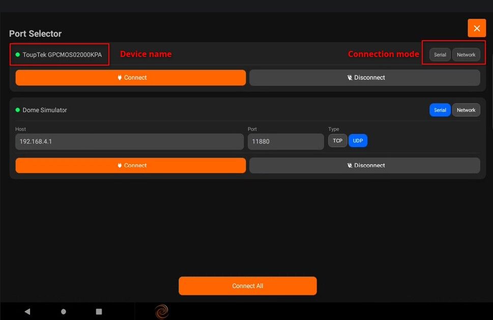
When connecting a serial device, you can specify the port by selecting from the drop-down or typing it in the text field
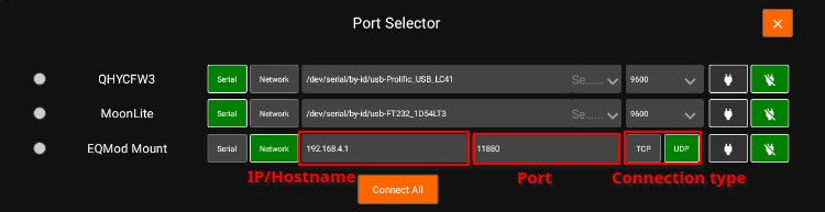
For network devices, you have to specify the host-name or IP of the device and the port. Also you can choose the network type (TCP/UDP).
5.2.4. Optical Trains
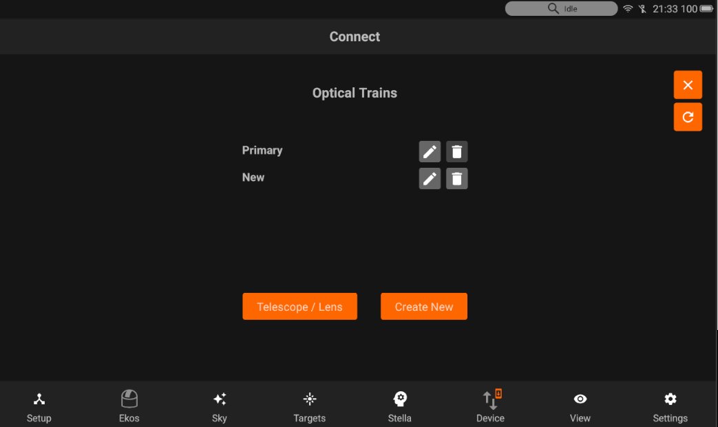
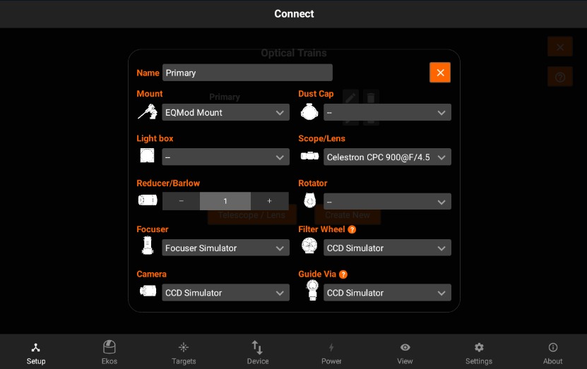
Optical Trains organize your equipment into separate unique optical paths. Each camera must have its own optical train. The following elements are specified in each train:
Mount: Select which mount to use. Typically, all optical trains in the same profile use the same mount.
Dust Cap: Select a mechanized dust cap if any (e.g. FlipFlat).
LightBox: Select a flat field lightbox if any (e.g. FlipFlat).
Scope or DSLR Lens: Select the scope or lens used in the optical path. To add, edit, or delete optical elements, tap the Telescope & Lens button.
- Reducer / Barlow: Select if any reducer or barlow is used in the train.
Reducer: By default it is specified at 1.0 which means that has no effect. Range is 0.1x to 0.9x.
Barlow: If the value specified is over 1.0x, then it is considered a barlow element (focal length is increased by this factor).
Rotator: Select a mechanized rotator if any.
Focuser: Select a mechanized focuser if any.
Filter Wheel: Select a filter wheel. This must be a standalone filter wheel connected to Stellarmate via USB. If you have a filter wheel that is embedded in a camera, leave this field mandatory.
Camera: Select imaging camera for this train. Each camera must have its own train.
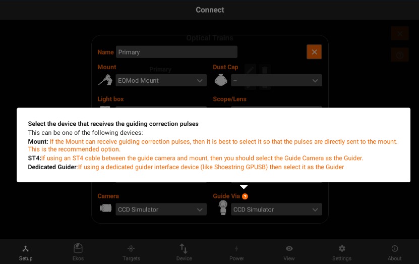
Guider: Select the device that receives the guiding correction pulses. This can be one of the following devices: - Mount: If the Mount can receive guiding correction pulses, then it is best to select it so that the pulses are directly sent to the mount. This is the recommended option. - ST4: If using an ST4 cable between the guide camera and mount, then you should select the Guide Camera as the Guider. - Dedicated Guider: If using a dedicated guider interface device (like Shoestring GPUSB) then select it as the Guider.
If a device provides more than one functionality, then it should be specified in all relative fields. For example, MoonLite Nightcrawler is a Rotator and Focuser at the same time, so we select NightCrawler under both Rotator and Focuser fields.
Once the optical trains are configured, specify which trains to use in each Ekos module. Typically, the Primary optical train is used in Capture, Focus, and Align modules while the Secondary train is used in Guide. Tap the help Button to view an external video tutorial on Optical Train.
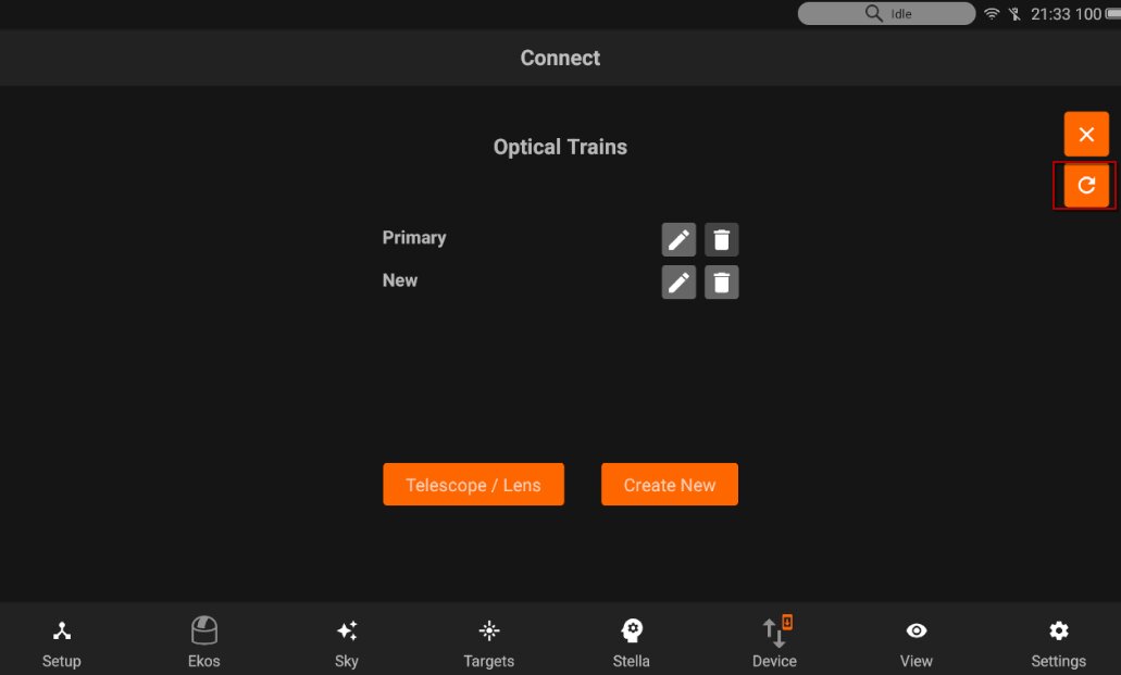
Tap the edit button and it will open the Optical train modal with the specific settings of a train.
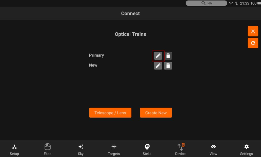
You can also reset the train configuration by pressing Red “Delete Icon” beside the name
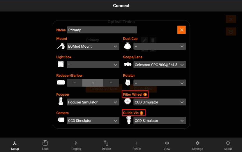
You can now view tool-tip for the description of some devices as shown in the images below:
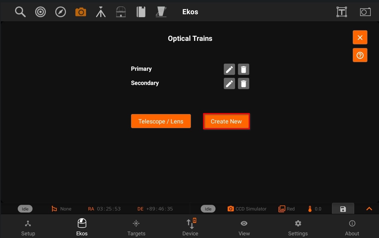
Tapping on Create new to creates a new train with a “New Train” name of previous / default settings.
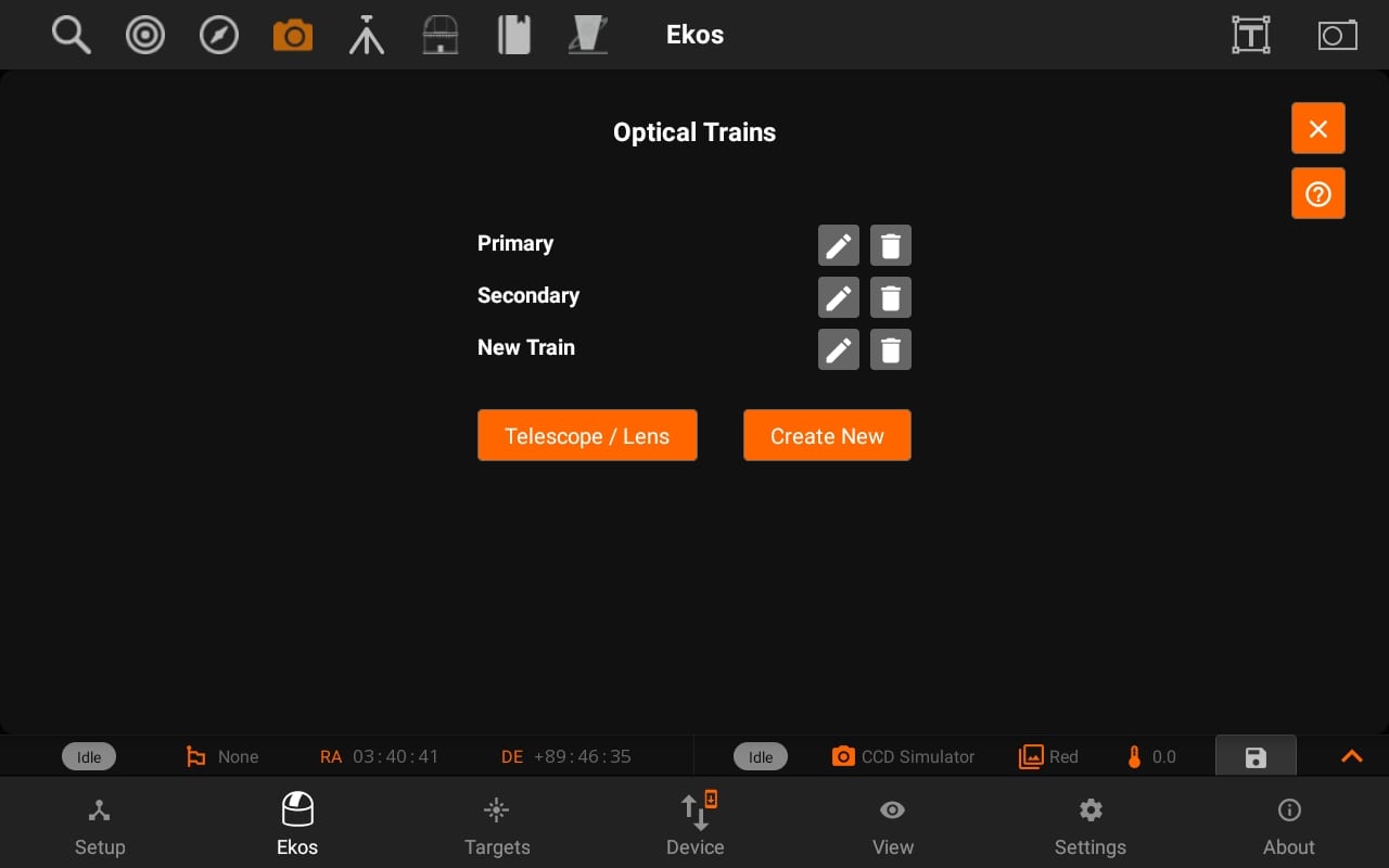
Telescope & Lens:
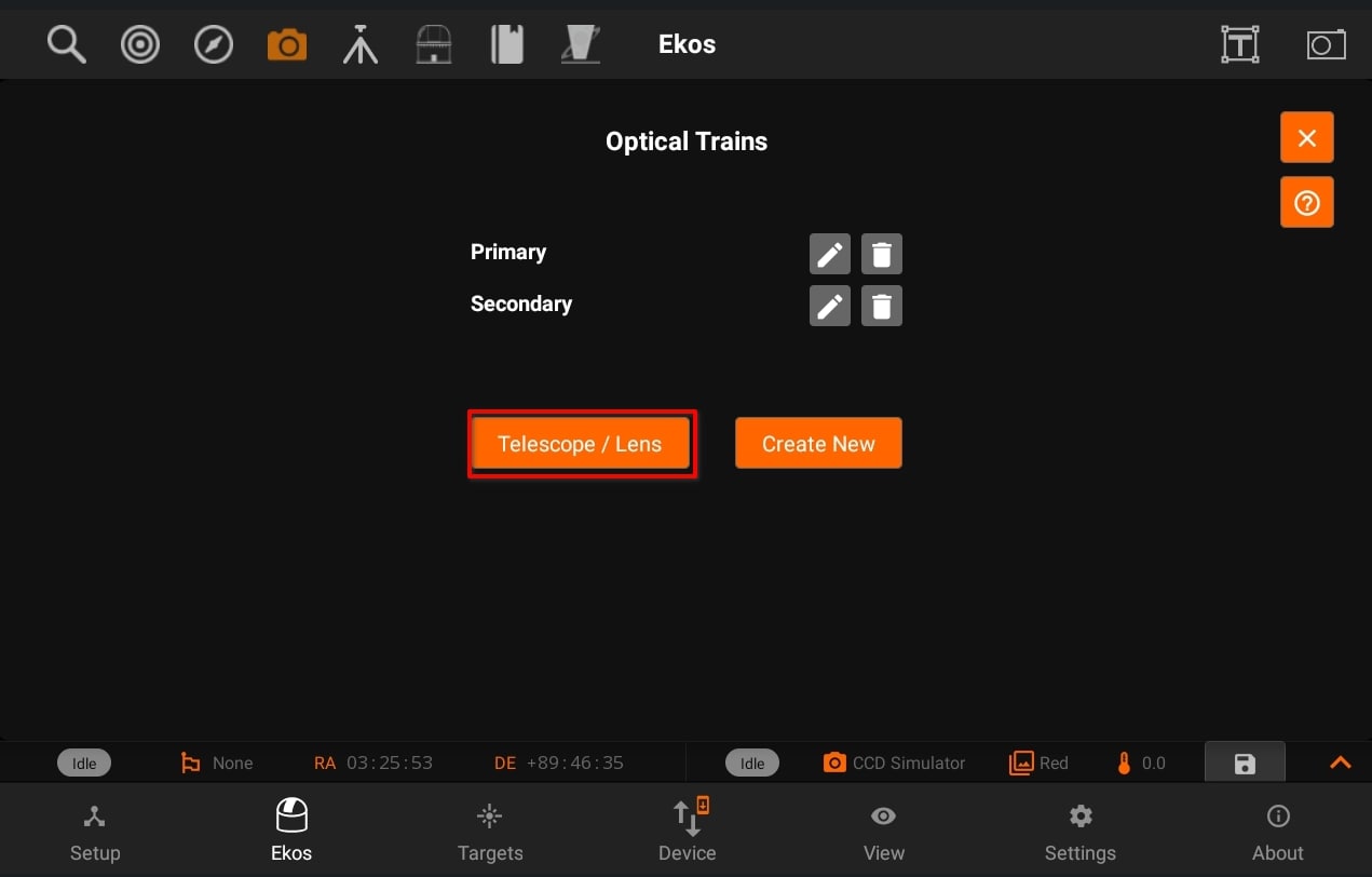
Displays Telescope / Lens View. So, you can Add / Update telescope and lens and then use those in different trains.
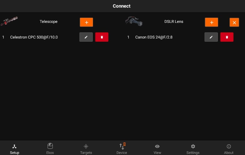
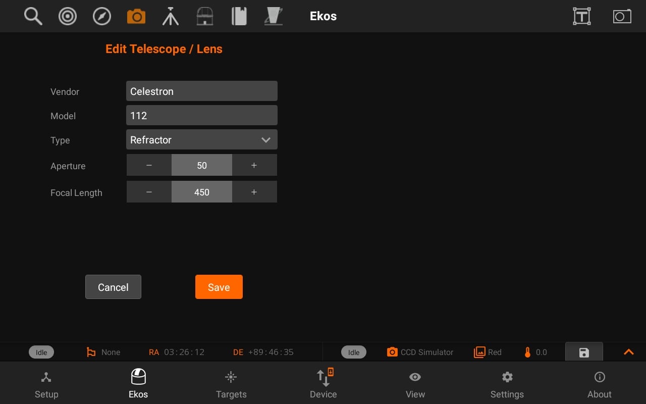
Tap on the Add/Edit button next to the telescope to edit the details of the telescope. All units are in millimeters.You can specify a Telescope and DSLR lens for your trains.
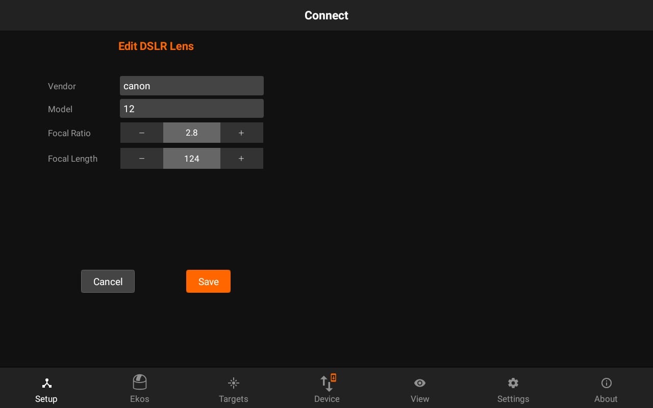
Similarly, you can add/edit DSLR lens and then use Scope/Lens in different Optical trains.
You can also access Optical train from the Setup Tab and Camera quick controls.
5.2.5. Weather Information
Weather Information are available in the setup page. The weather bar displays current weather information for the surrounded region. It provides the current state of the weather, temperature, wind speed, humidity and the Bortle Class. The Bortle Class is a measure of the brightness and observation of the sky relative to light pollution. Bortle Class 1 is ideal and 9 is the worst.
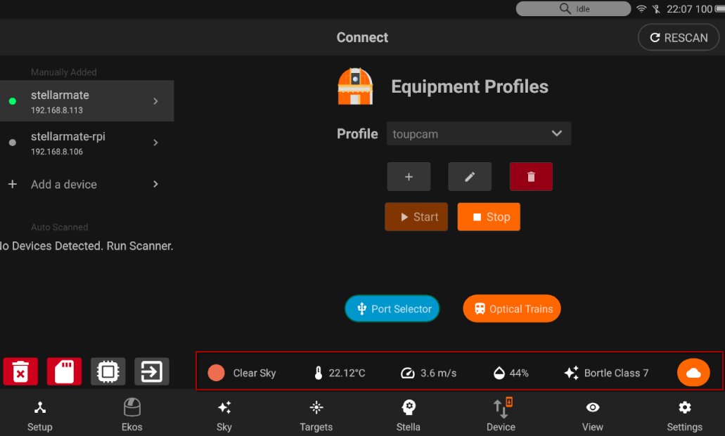
The cloud button displays the 3-hour cloud map based on your current location.
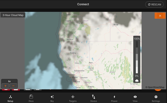
The visibility bar displays the percentage of cloud coverage over the map.
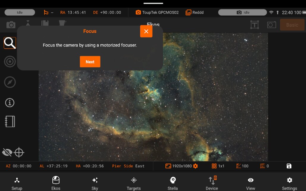
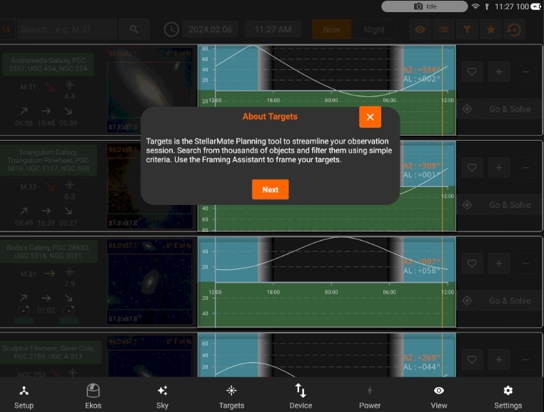
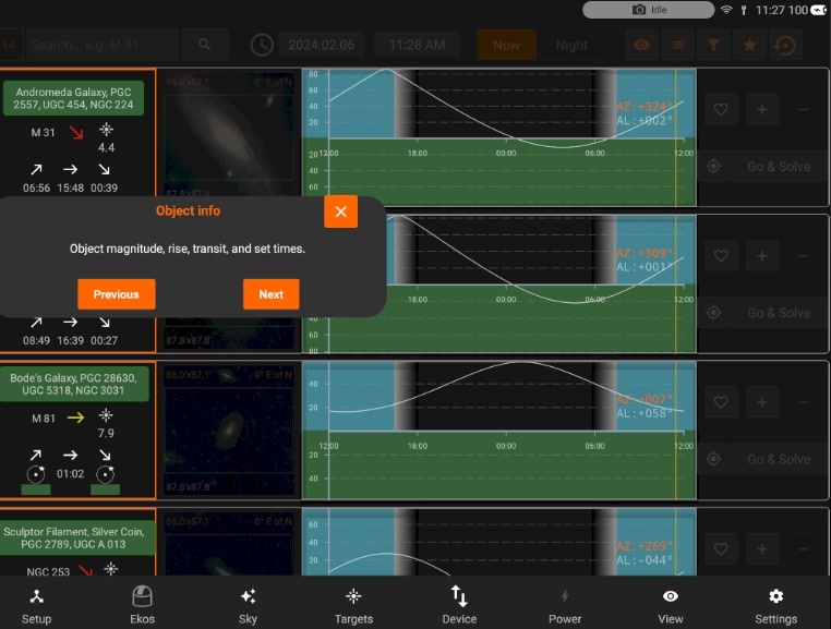
5.2.6. Tour Guide
If you would like to take a tour guide, you will see a pop up whether to continue Tour Guide or later.
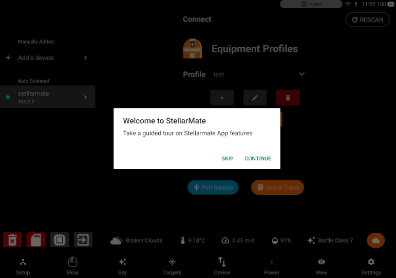
Currently Tour guide is available for few important features i.e Setup, Ekos & Targets.
Tour Guide can be seen in the few images below:
For Setup, you can tap “Next” to proceed to the next tour zones.
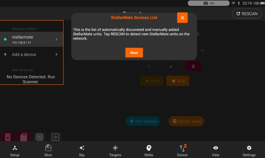
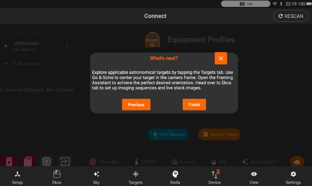
On tap “Finish”, the tour guide for specific tap will be considered as completed. You can also tap “X” during Tour guide to close it. That will also be considered as completed.
ON tap “Previous” button, to view the previous tour guide zone.
In Ekos, one line description of modules and Quick controls is explained.
In Targets, the main features are explained as shown in the few images below.
5.2.7. DSLR Setup
StellarMate supports many DSLR cameras from various manufacturers. When a DSLR is detected, StellarMate attempts to identify it and then fill in the necessary metadata required to run the camera. These include width and height in pixels, and the pixel (pitch) size in microns. If StellarMate is unable to find this information, a DSLR Setup button is displayed in the Equipment Profile page. Tap it to enter the information manually.
Once your DSLR is connected, it will ask you to setup it.
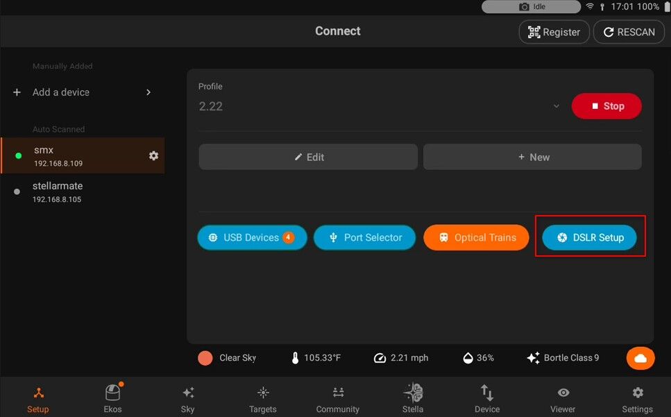
After configuring it, you can tap the save button.
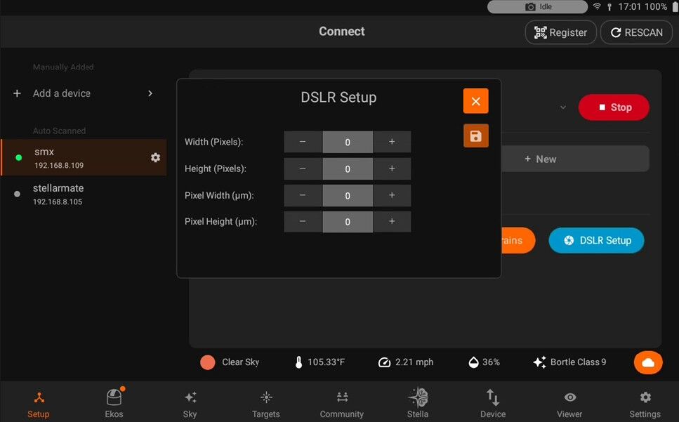
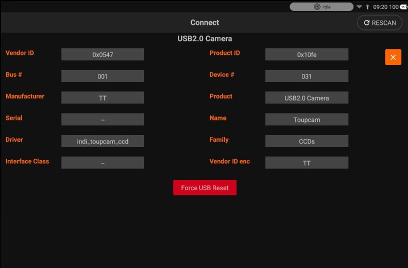
5.2.8. USB devices
Now you are able to view the connected devices and it’s details from StellarMate App.
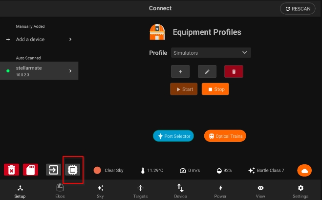
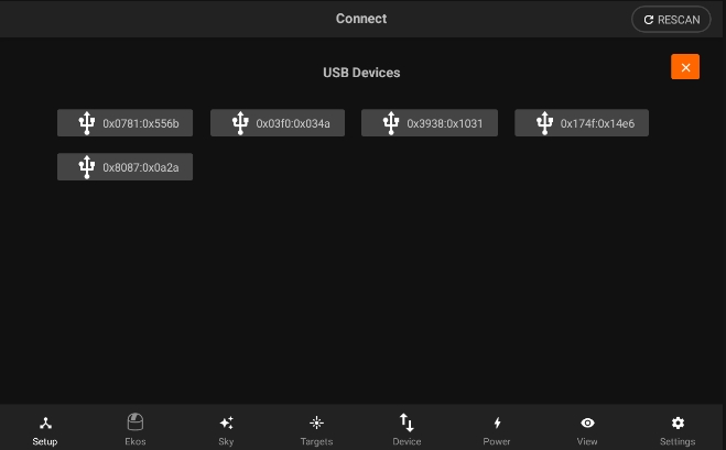
Pressing on each Device list, you will be able to the it’s information.
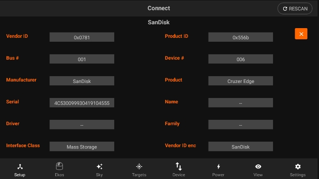
You can also reset a device connected via USB by pressing on the “Force USB Reset” button.
5.3. Ekos
Ekos is where all the astrophotography workflow takes place.You can control all your equipment, run sequences, and automate your workflow with the scheduler.
It is divided into different sections to facilitate access.
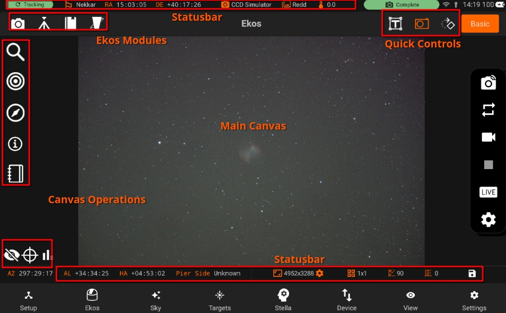
Main Canvas: Displays the captured images.
Canvas Operations: Control image histogram, toggle overlays, or display the summary view. Includes Advanced controls for Focusing, Guiding, Alignment
Ekos Modules: Capture, Mount, Observatory, Scheduler, and INDI Control Panel.
Quick Controls: Quick access to Camera, Mount, and Rotator (if available) operations. With Camera quick controls, you can capture previews, videos, and toggle live stacking. Mount quick control provides mount speed & directional controls in addition to tracking, goto, and parking operations.
Status Bar: Divided to Mount and Camera status bars to display current status and any relevant information. Two status bars. One on top and one at the bottom. Also includes Device Battery level, WiF, Ethernet status and a badge with shows overall Status of modules whether Capurting, Aligning etc.
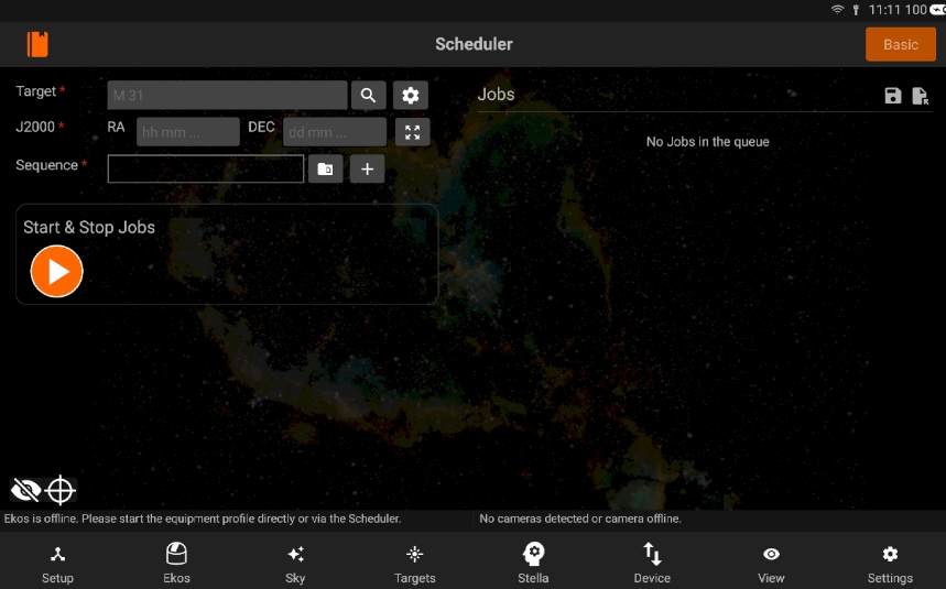
Ekos modules and Quick Controls are only available after an equipment profile is started in the Setup screen. However, if no equipment profile is started, you still have access to the Scheduler module as it can be used to schedule your targets and command startup and shutdown of equipment automatically. From the scheduler, you may select targets and sequences to create jobs. Job constraints impose conditions that must be met. Once the scheduler is running, it will select the best targets for imaging and would automate the rest of the workflow without any operator intervention.
When an equipment profile is started, the Ekos modules are activated:
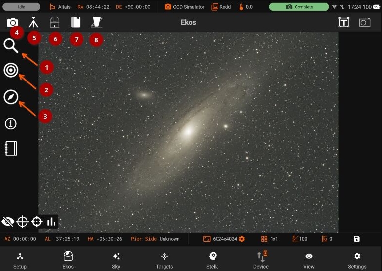
Focus: Focus your camera either automatically via an electronic focuser, or manually by adjusting the focus while framing, or by using Bahtinov Mask Assistant. Create presets for different configurations and set advanced settings to control the star detection and focusing algorithms.
Align: Align your mount to get highly accurate GOTOs and to ensure you target is always in the center. You can also load an existing image to plate solve and then command the mount to go to the exact center in the sky. Perform Polar Alignment to ensure sharp images for long-exposure astrophotography.
Guide: Guiding enables long-exposure astrophotography by ensuring your mount tracks accurately with time. It can automatically select and lock a guide star and send correction pulses to the mount to keep it always centered.
Capture: Manage capture presets and jobs. Run sequences, adjust filter offsets, and manage your dark library.
Mount: Manage Meridian Flip & Limit settings.
Observatory: Control Dome or Roll-off observatories. Command mechanized Dust Caps.
Scheduler: Select targets and specify startup conditions and constrains, then let Ekos manage the rest.
INDI Control Panel: Direct access to all INDI devices and their properties.
Quick Controls are simplified quick-access settings for the camera, mount, and rotator located on the top-right panel. They can be toggled at any time. Once toggled, the corresponding control is overlayed on the top of your existing view where you can quickly and efficiently control your devices.
Mount: Toggle parking & tracking. Adjust speed and use directional keys to move the mount just like the handset. Issue GOTO and SYNC commands by searching for objects.
Camera: Capture previews, record videos, and toggle live stacking.
Rotator: Control absolute position.
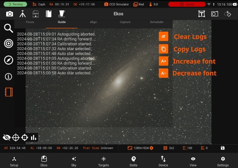
Logs Quick access to Ekos logs. All Ekos logs are now consolidated in an easy to access view. Simply swipe right from the edge of the left screen to show the logs. Depending on which module you are currently using, the active logs would be displayed.
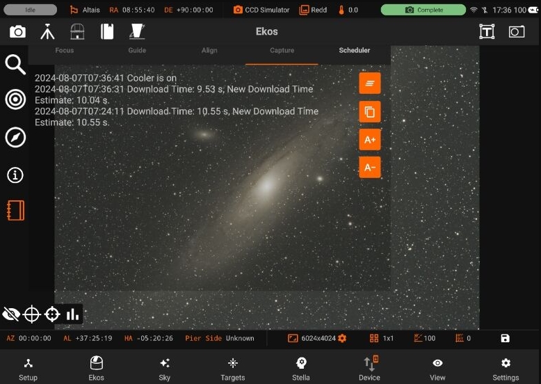
You can also:
Clear the logs
Copy the logs text
Increase/Decrease font size
Save Images
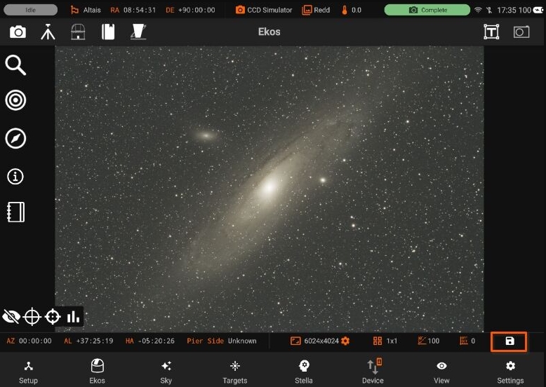
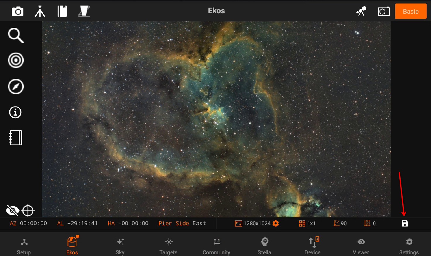
All canvas images can be saved directly to the phone/tablet image Gallery by pressing the Save icons button at the bottom-right. The image name is auto-generated with a timestamp.
5.3.1. Basic Mode
StellarMate App Ekos module operates in Basic or Expert modes. Basic mode is for beginner users. It has a simple UI with basic settings. It works step by step. You can navigate to any step at anytime. You can easily switch between Basic/Expert mode.
Following are the steps: * Polar Alignment * Targets * Focus * Guide * Capture * Summary
5.3.1.1. Polar Alignment
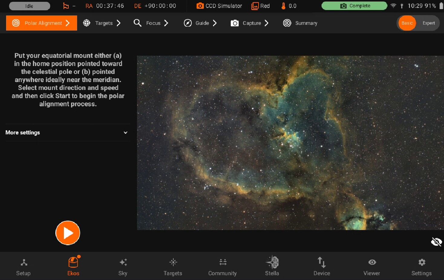
To manage the polar alignment, use the Polar Alignment controls. Note that Ekos performs two mount rotations during this process.
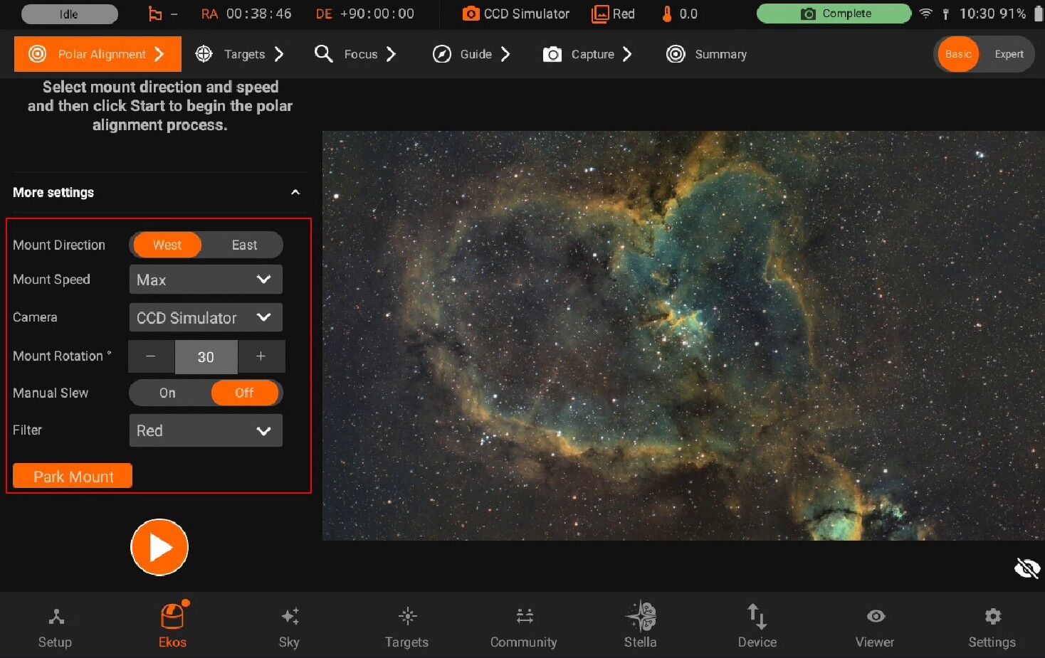
You need to set the desired speed, angle, and direction (West/East) for the mount rotation. Press play to begin the alignment.
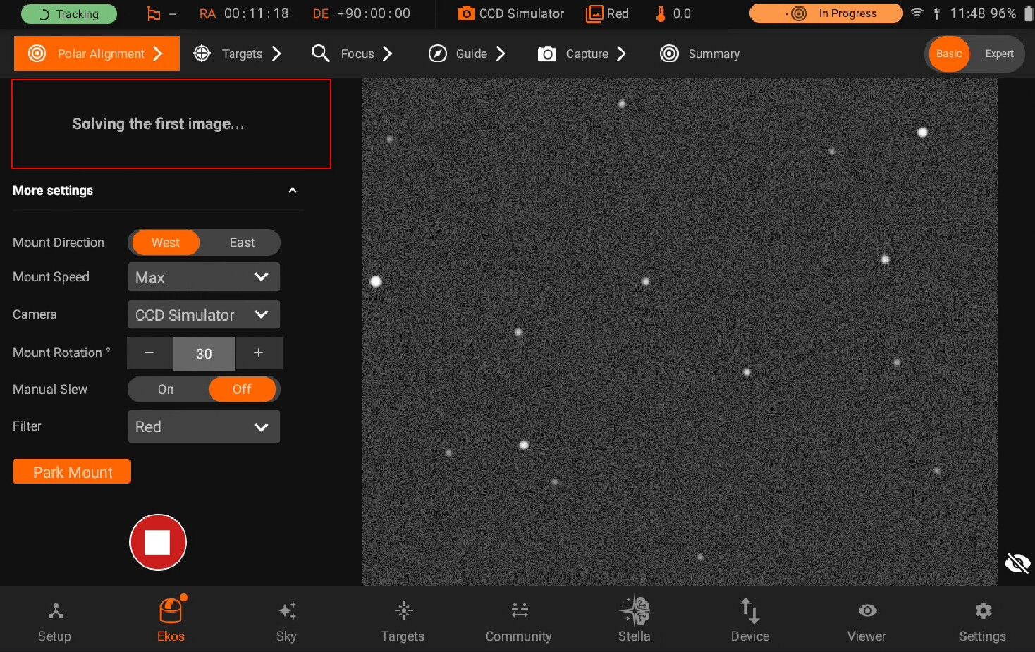
Then, follow the guided instructions provided on screen until the Polar Alignment process is complete.
5.3.1.2. Targets Selection
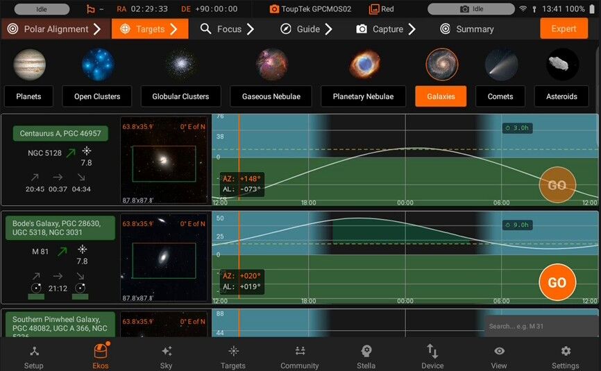
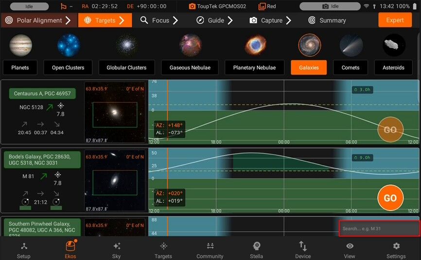
In the Targets Selection mode, you can search for various astronomical objects across different classes.
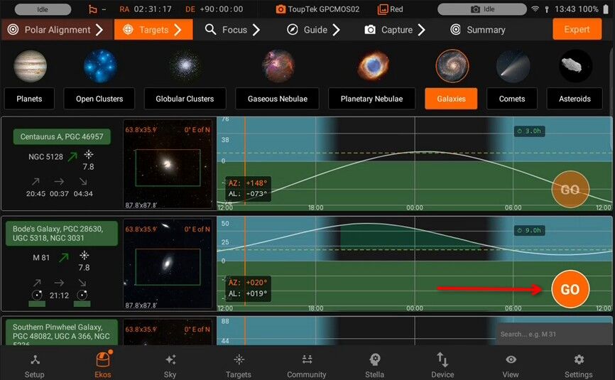
You can view the Object Info for each target. It includes object designations, observability, rise, set times and also Altitude vs. Time chart to assess the observability data for any celestial target.
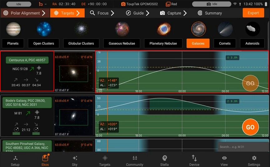
Use the GO button for slewing and centering the target.
5.3.1.3. Focus
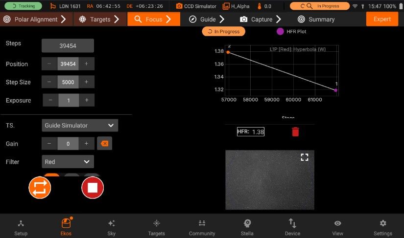
To focus your target effectively, you can utilize an electronic focuser for achieving crisp images. Within the Focus Controls, you should first frame a target area containing clearly resolvable stars using the loop button.
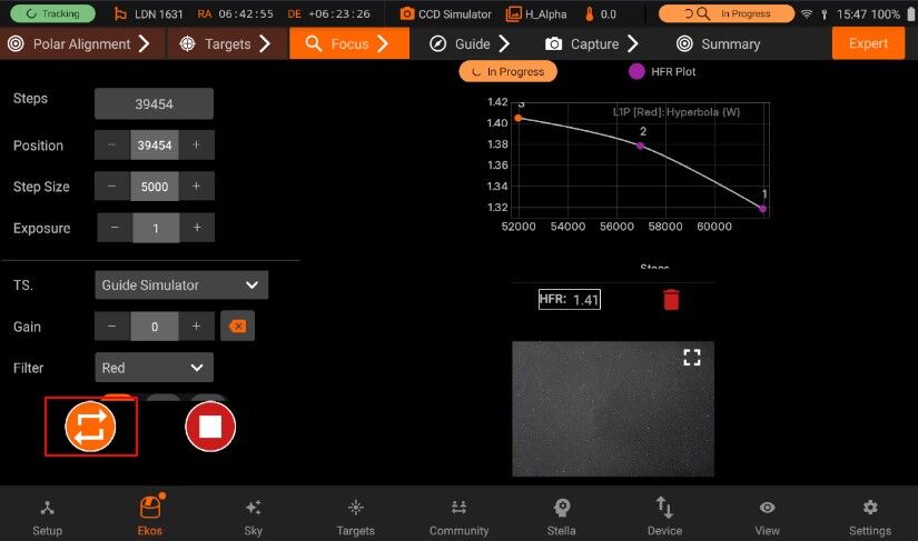
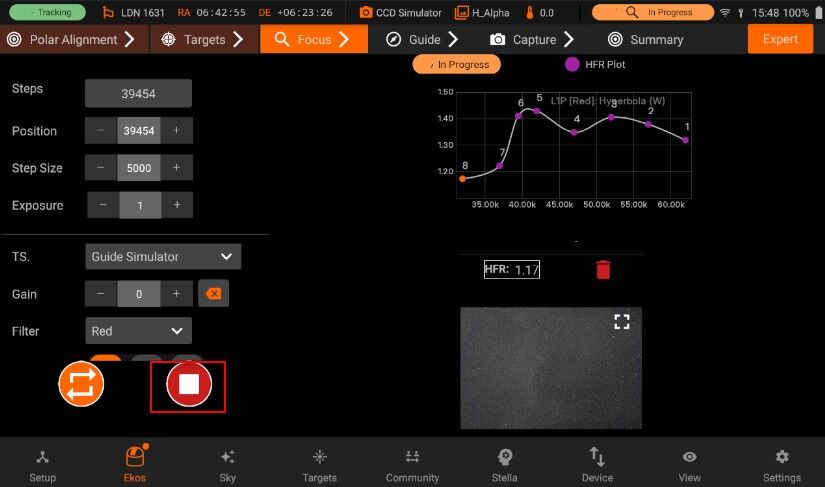
After setting an appropriate step size for your equipment, press play to initiate the fine autofocus process. You can monitor the progress using the Focus Graph, which displays the HFR versus the focuser step position, illustrating the focus quality; the autofocus routine works by generating a V-curve on this graph to pinpoint the Critical Focus Zone (CFZ). When simply looping exposures, the HFR for each frame will be plotted here. Additionally, keep an eye on the actual star sharpness in the Focus Image display, which can be toggled to full screen for a more detailed view.
5.3.1.4. Guide
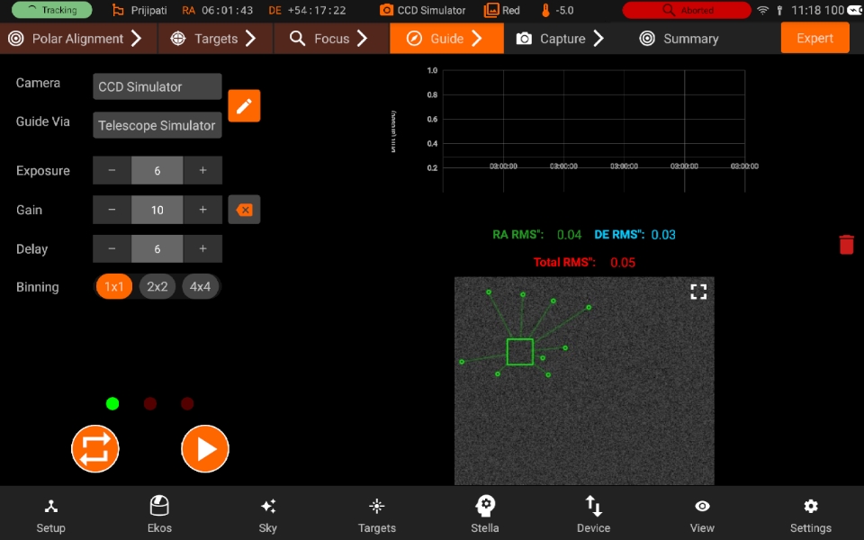
Auto Guiding is essential for keeping targets accurately centered during long-exposure imaging, typically achieved using a dedicated guide scope or an Off-Axis Guider (OAG).
On the left side, Guide Controls where you can adjust the guide camera settings. You’ll also need to specify how Ekos sends guide corrections by setting the ‘Guide-Via’ option, usually to the mount (the default) or via an ST4 connection.
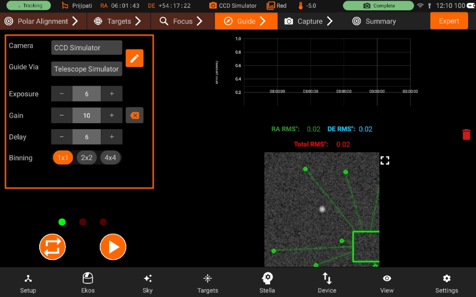
Use the framing button to ensure the guide stars are clearly resolvable.
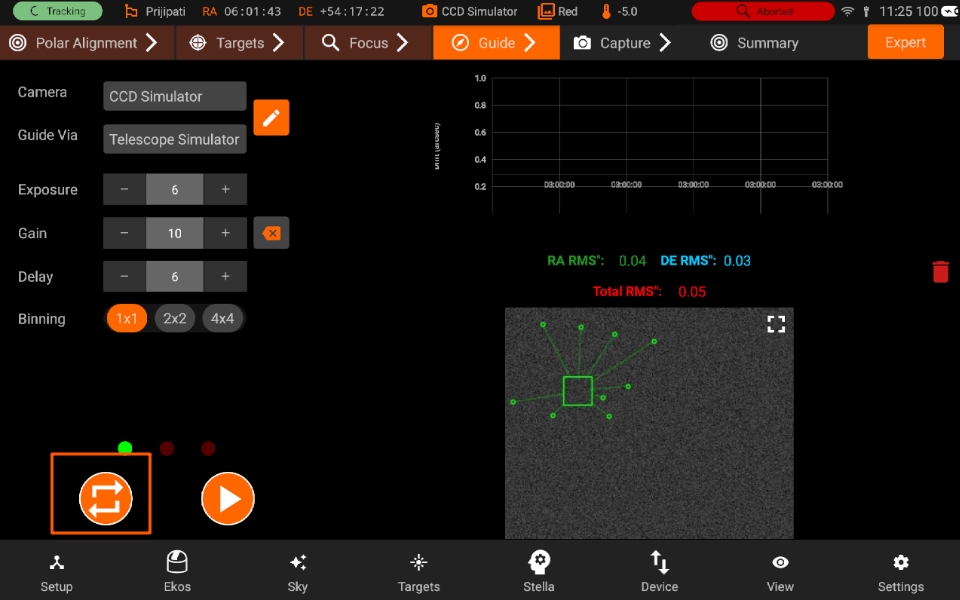
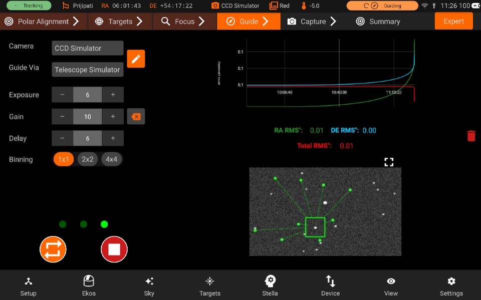
Once configured, press the play button to initiate the calibration sequence followed by active autoguiding. You can monitor the performance using the Guide Chart, which presents a trend graph illustrating tracking accuracy through RMS errors over time for Right Ascension (Green), Declination (Blue), and the total combined error (Red). Additionally, the Guide Image provides a visual representation from the guide camera, featuring a multi-star tracking overlay; you can toggle this view to full screen for a more detailed inspection of the guiding process.
5.3.1.5. Capture Planner
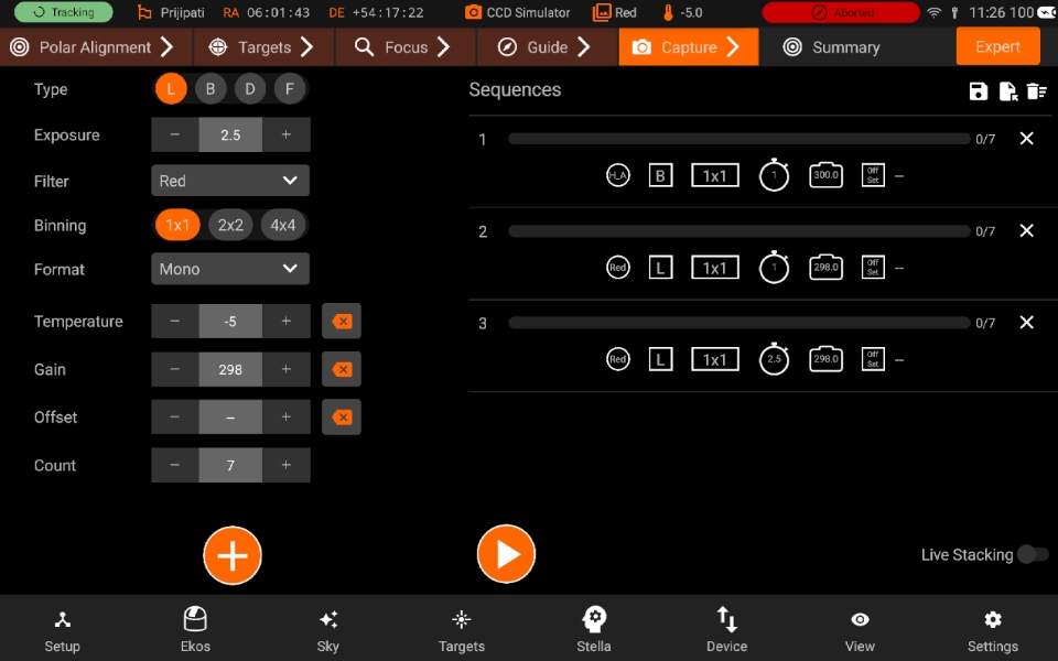
The Capture Planner is the central hub for defining your imaging session. Here, you can configure image capture settings such as exposure duration, filter choice, binning, and more, adding these configured jobs to your overall sequence. Within the Capture Controls, you’ll specify the details for each job, like setting the frame count, and then use the ‘add’ button to include it in the sequence queue.
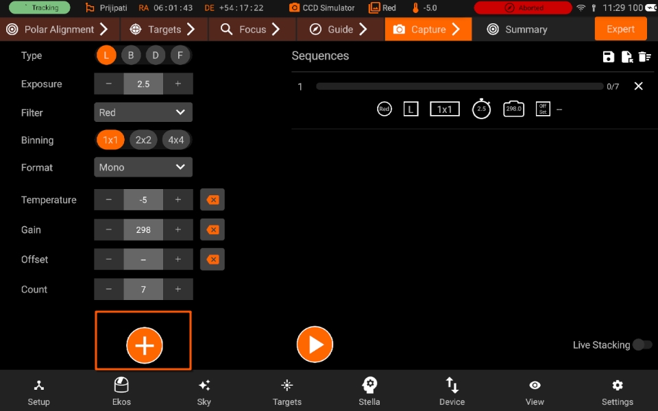
To handle your different imaging plans, the Manage Sequences section allows you to Save, Load, Delete, and Organize your imaging sequences for reuse or modification.
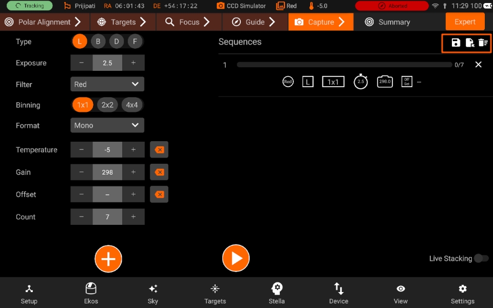
Finally, under Capture Actions, you press the ‘play’ button to start the entire imaging sequence.
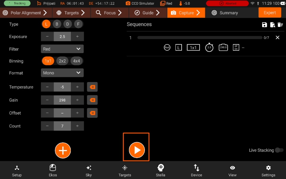
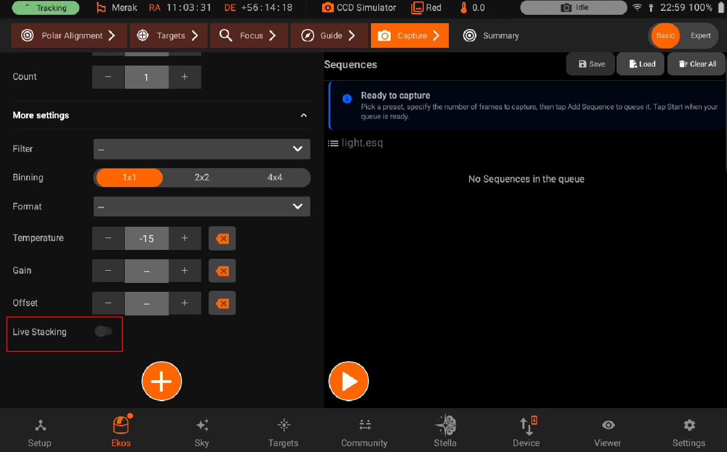
You can toggle the live-stacking feature on or off. Enable this option to see combined images generated in real-time. Individual frames captured during the sequence will be saved separately.
5.3.1.6. Summary View
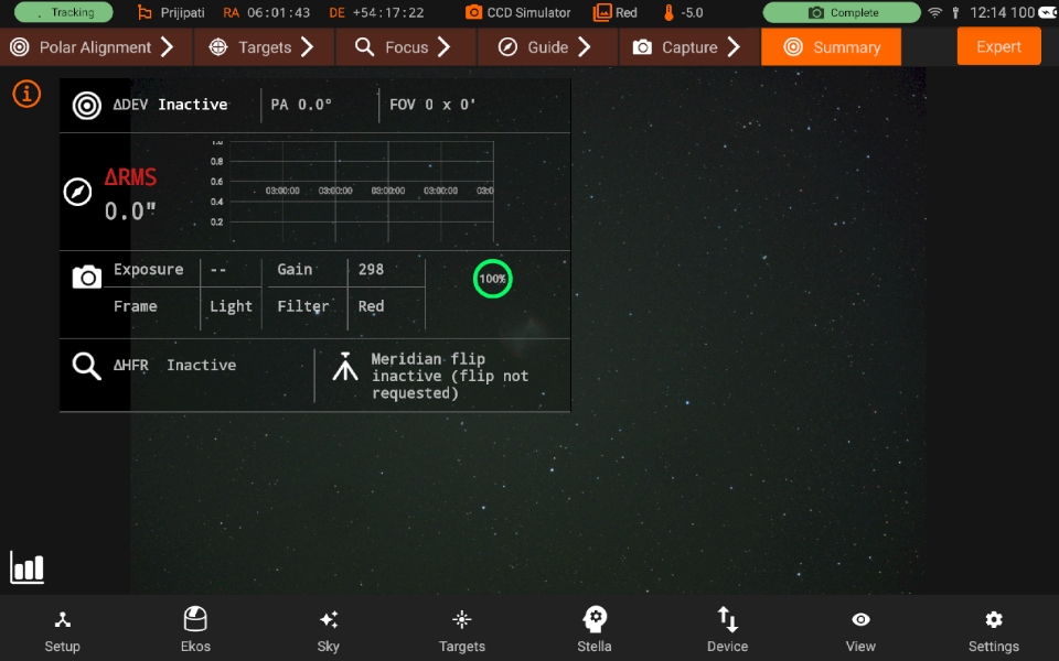
In the Summary view, monitor all key operations: guiding, focusing, alignment, and image capture. Captured images are also displayed in this view.
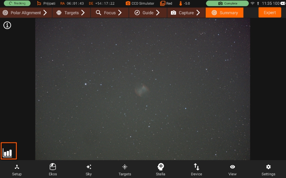
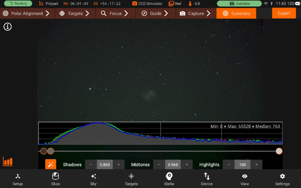
Within this view, you can toggle the Histogram display. This tool allows you to inspect the tonal distribution of your images and adjust the shadows, midtones, and highlights, but note that these adjustments are applied only to the individual sequence images and do not affect any images generated through live-stacking.
5.3.2. Canvas
Canvas is the primary imaging display area where images, video, and live stacking takes place. The canvas operations are divided into upper and lower canvas controls. The upper controls include dragabble widgets for Focus, Align, and Guide modules along with Summary and Log views. Lower canvas controls are used to toggle overlays, command GOTOs by tapping and holding anywhere on the image, and to display the histogram and HiPS overlays for the image.
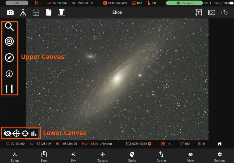
Upper Canvas
Focus
Align
Guide
Summary View
Logs
Lower Canvas
Histogram
HiPs Overlay
Crosshair
Target GOTO
Hide/Unhide the Lower Canvas
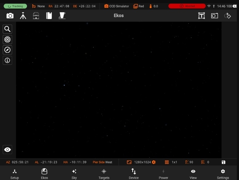
You can center the mount to a specific target in the main image if plate-solving was successful. From Ekos Align module, Capture and Solve an image. If successful, an orange align icon is displayed in the Main Image View indicating that solving is successful. For any subsequent images captured and displayed in the Main Image View, you may now select the target by tapping on it. A red bullseye animation designates the target. Control image histogram, toggle Overlay or display the summary view.
5.3.2.1. Summary View
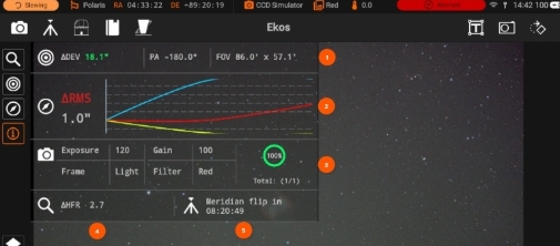
The summary view includes the gist of your astrophotography workflow so you can always take a quick look at the most important parameters without navigating to other screens. Depending on which Ekos modules are active, the information may include the following:
Alignment
Total deviation error in arcsecs. The deviation is updated when you perform a capture and solve operation.
Position Angle (PA) in degrees East of North.
Field of View (FOV) in arcminutes.
Guide: Total RMS error in addition to the guide deviation chart.
Capture: Current sequence settings and a progress indicator. Two timers are displayed to the right of the progress indicator when a sequence is running:
Top timer: Sequence job timer countdown. This is the countdown until the current active sequence is complete.
Bottom timer: Overall timer countdown. If you have multiple sequences, the timer indicates the estimated time until all sequences are complete.
Focus: Half-flux-radius (HFR) measurement.
Mount: Current meridian flip status.
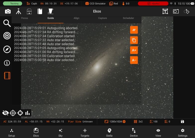
5.3.2.2. Logs
You can view Logs of modules which includes Focus, Align, Guide, Capture and Scheduler.
5.3.2.3. hiPs Overlay
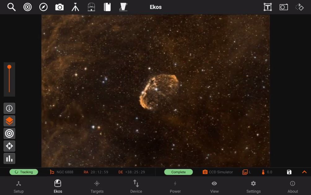
Toggle Overlay to increase the Hips opacity. image It is only available when WCS is enabled, image is plate-solved and once your Camera FOV is 60 arcminutes or more.
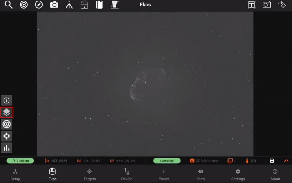
Once preview is captured, you can toggle it and increase/decrease the HiPs opacity.
5.3.2.4. Histogram
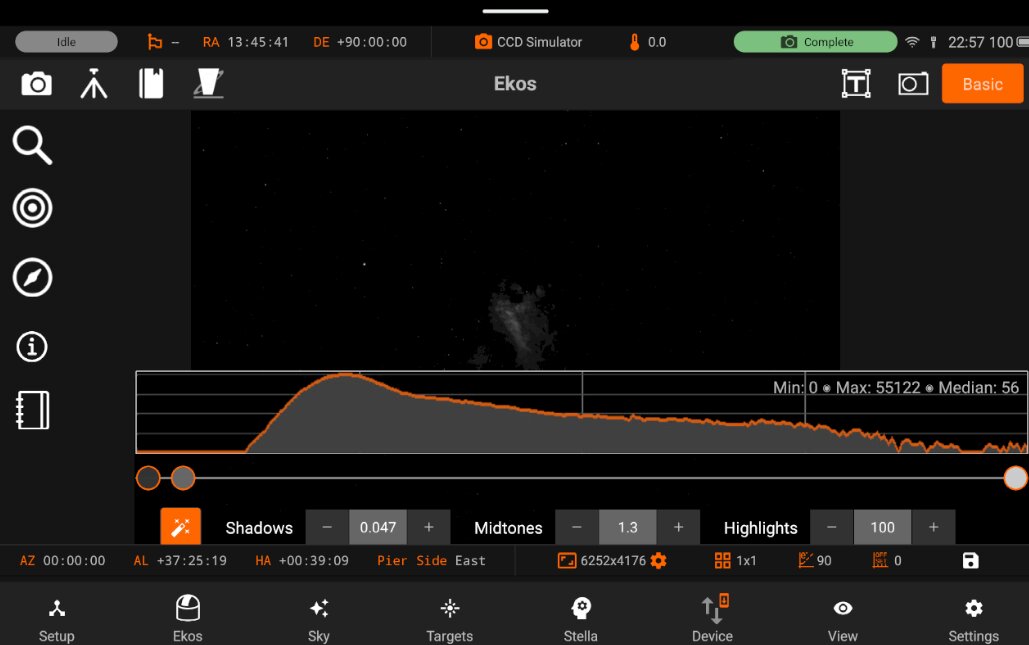
Histogram When available, clicking the histogram button in the main image view toggles the non-linear histogram. The histogram is generated for both mono and rgb images.
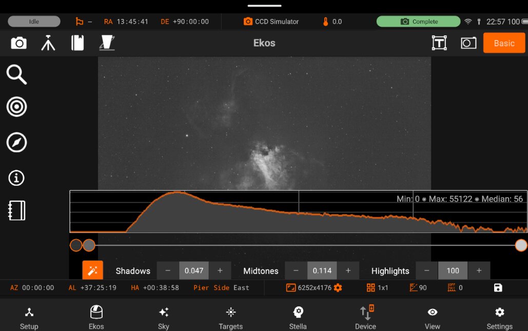
The sliders in the middle control the shadow, midtone and clipping parameters. You can move them, left or right, and as you move them, a real-time (but low resolution, for compute reasons) preview of the stretch is shown. When you let go of the slider, the setting is kept, but the button returns to the middle of its range so that you can make further adjustments–there is very little screen space. You can tell the setting is kept as the number shown should not change after you release the button. Think of these as “relative” sliders. Also, when you let go of the slider, you also get the full-resolution image, instead of the real-time approximation.
5.3.2.5. Target GoTo
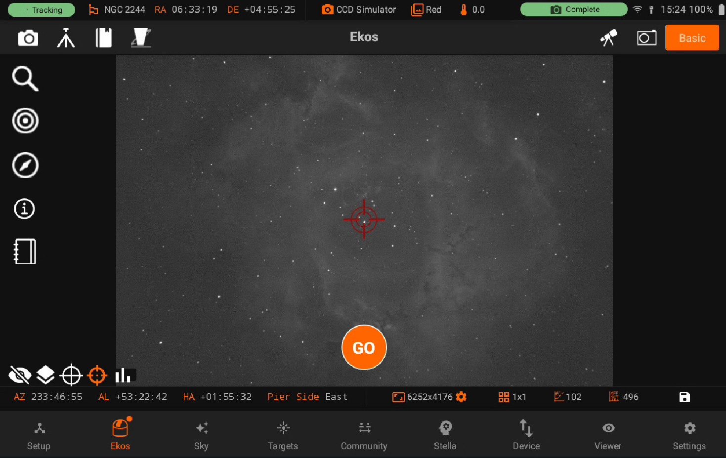
Canvas on Main Image You can center the mount to a specific target in the main image if plate-solving was successful. From Ekos Align module, Capture and Solve an image. If successful, an orange align icon is displayed in the Main Image View indicating that solving is successful. For any subsequent images captured and displayed in the Main Image View, you may now select the target by tapping on it. A red bullseye animation designates the target.
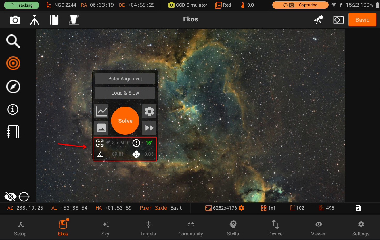
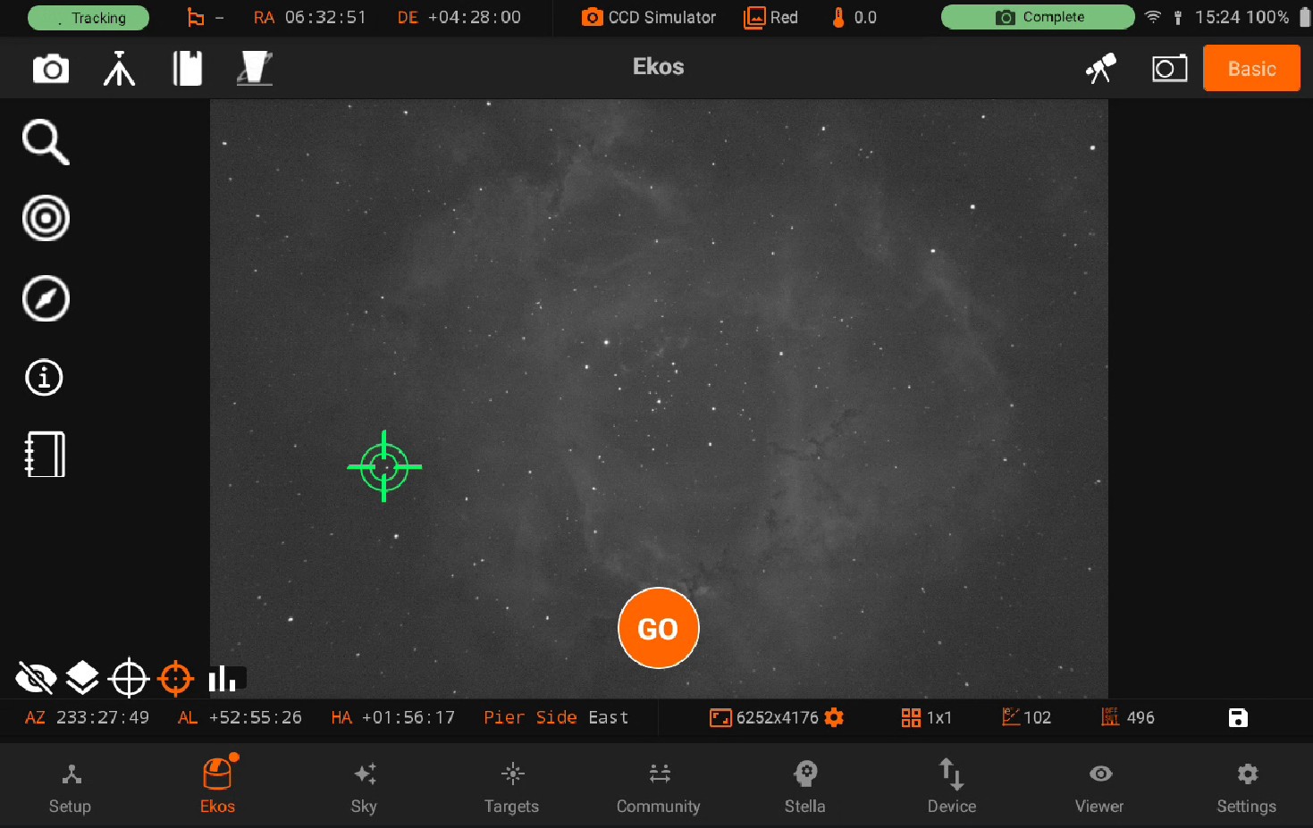
Tap GO button to command the mount to slew. If successful, the indicator icon changes to yellow and once motion is complete, it switches to green. Capture a preview to verify the mount indeed centered the target as desired. Repeat if necessary. Hold on your desired target, mount will star moving to that specifc target. Yellow animation will be appeared while it in in process. Can also be seen in the below images.
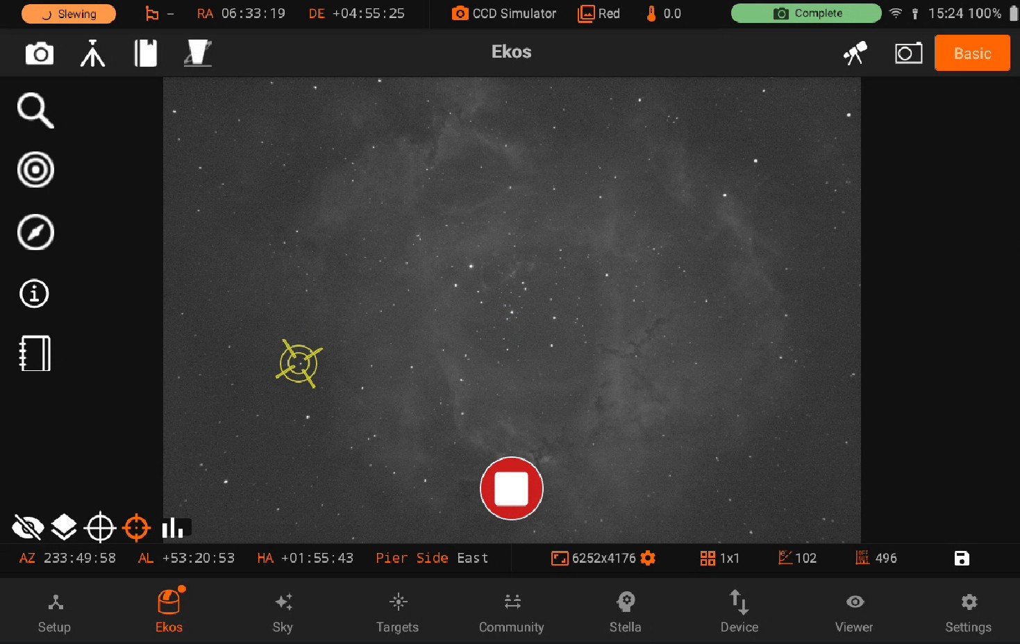
On success, the animation will turn to green. On capture new image, the target lock animation will be reset to default.
5.3.2.6. Crosshair
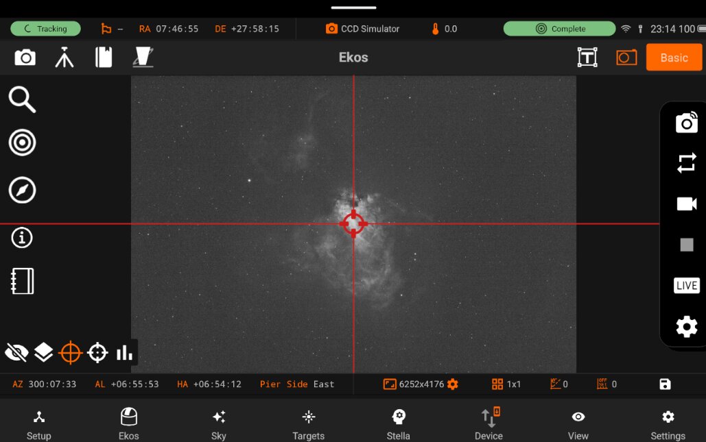
Crosshair Use crosshair on captured image, which is appeared on the center of captured image. Once it is toggled, you can see the crosshair on the image.
5.3.3. Status bar
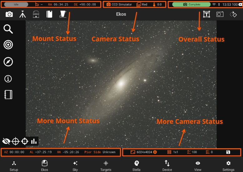
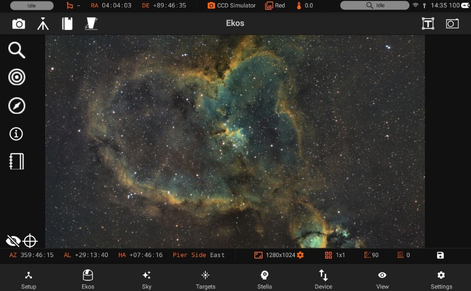
The important information of Mount and Camera is shown at the top and at the bottom:
Top
Bottom
5.3.3.1. Top
Mount Status
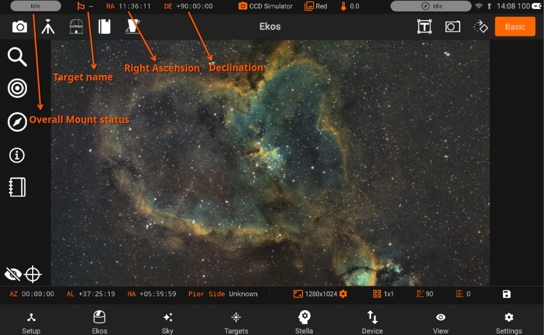
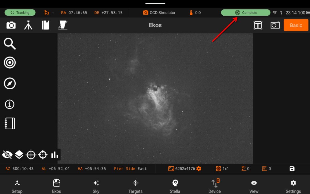
Mount status: Displays current operational state (PARKING, UNPARKING, SLEWING, or TRACKING).
Target object: Shows name of currently selected celestial object.
R.A.: Indicates current Right Ascension coordinates of the mount.
DEC.: Indicates current Declination coordinates of the mount.
Camera Status
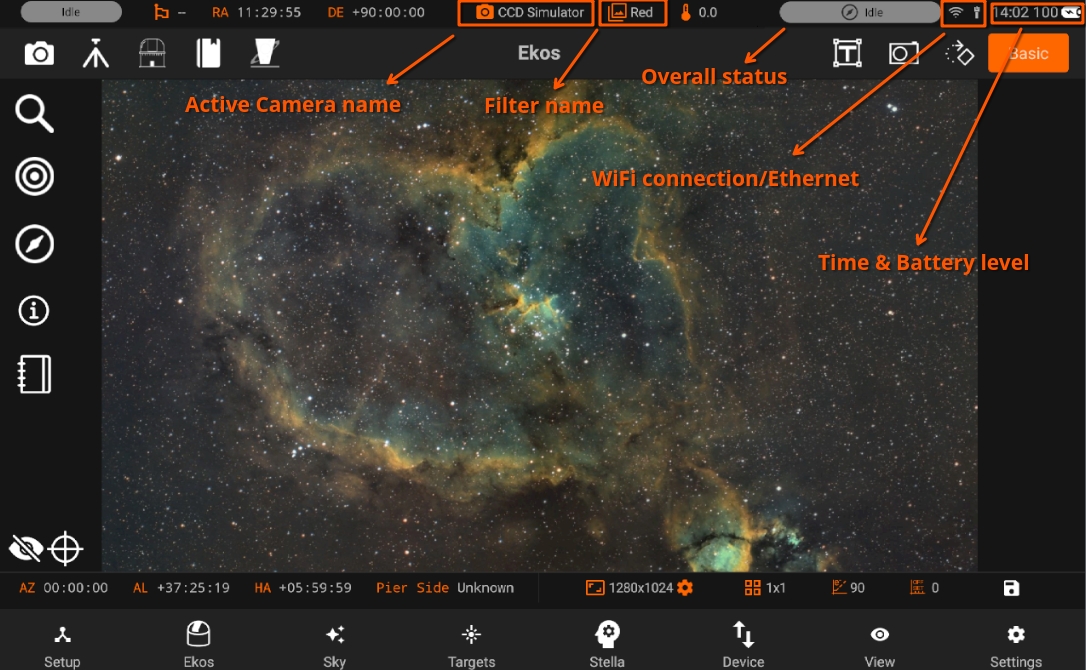
- Shows the camera’s current operational state:
Capturing: Camera is actively taking images
Complete: Image or sequence capture successfully finished
Idle: Camera is ready but not currently capturing
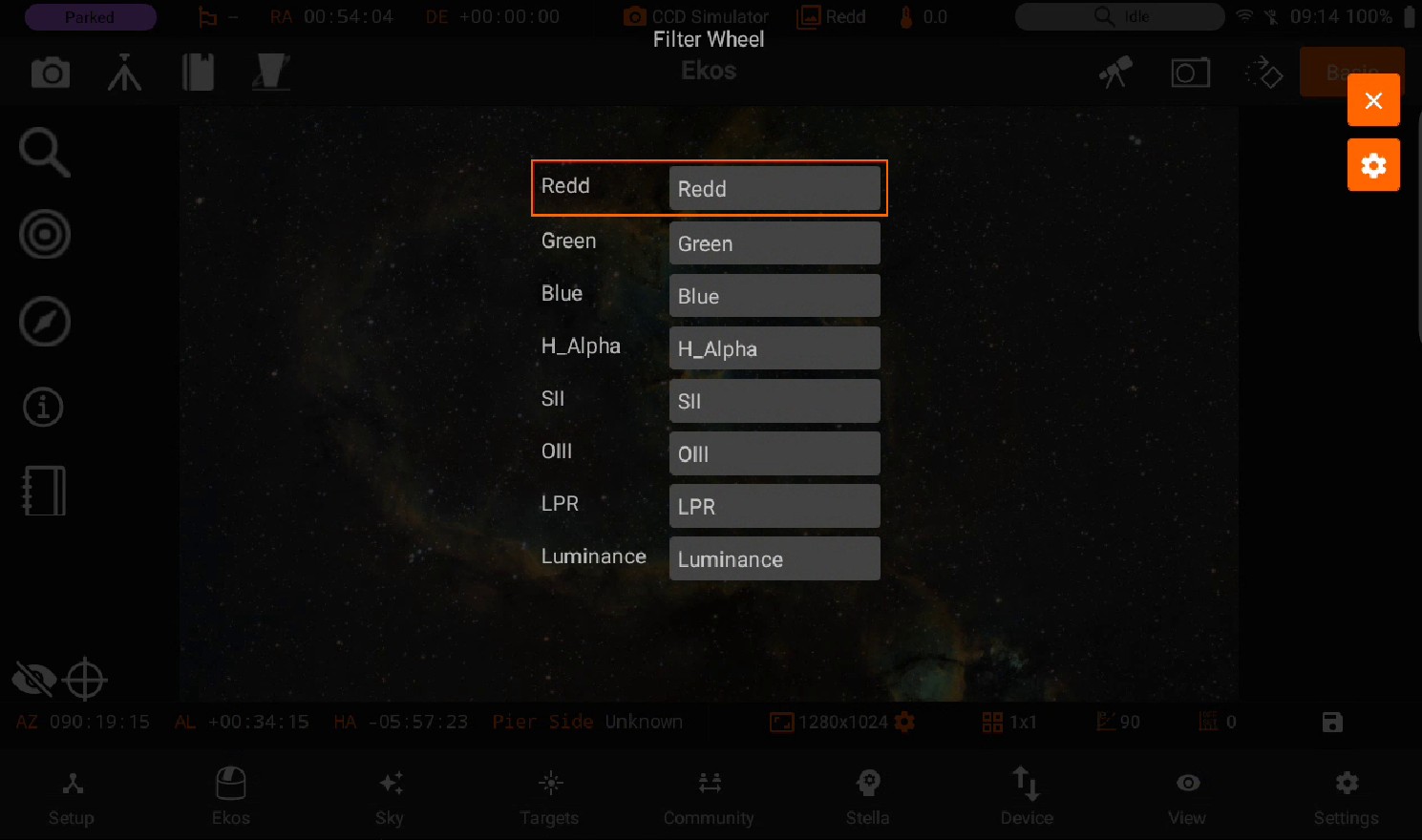
Displays the camera name and active filter name.
Once you press on the filter name, you will be able to edit Filter names.
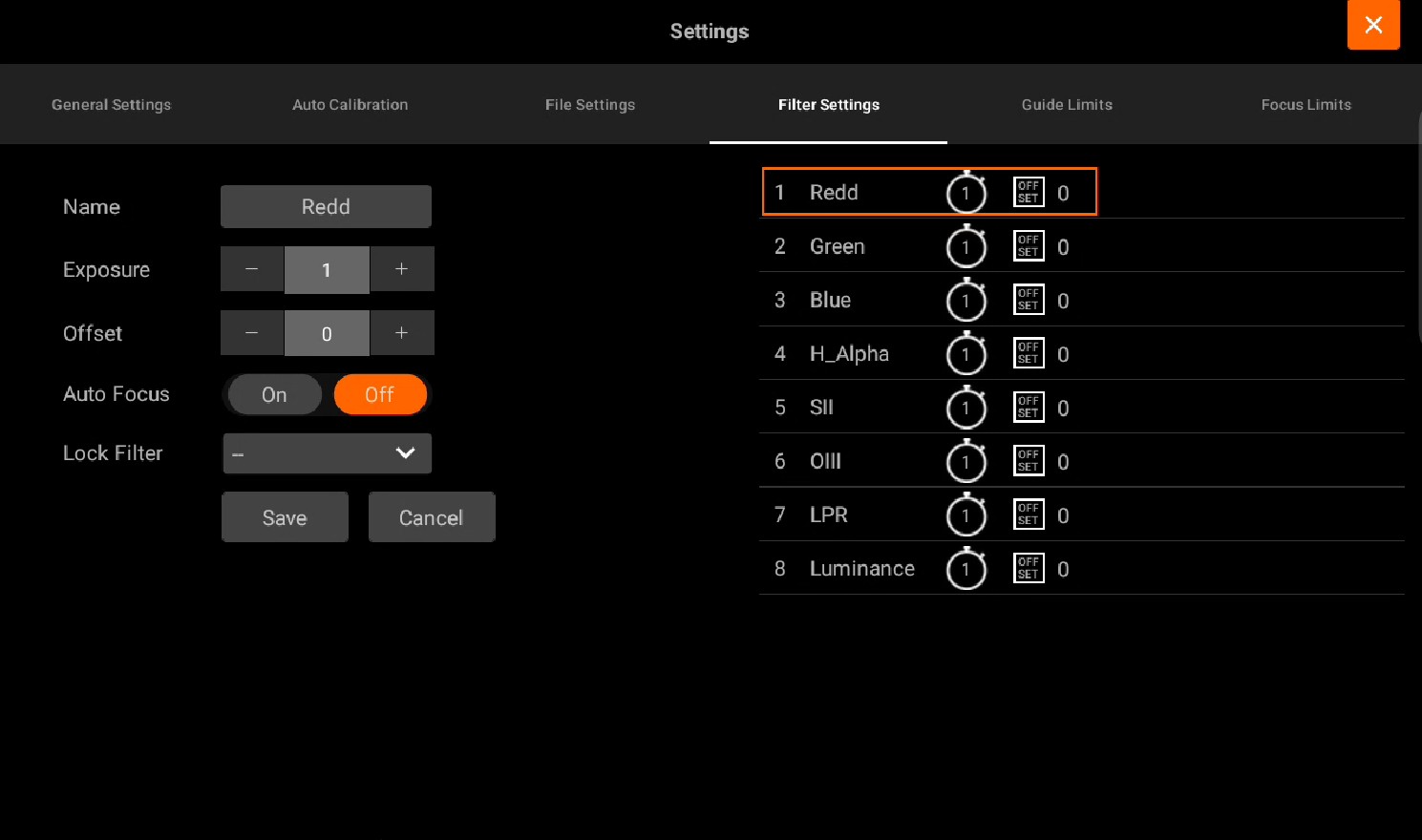
You can also access Capture settings by pressing the Cog wheel button on the top right.
Build Filter Offsets
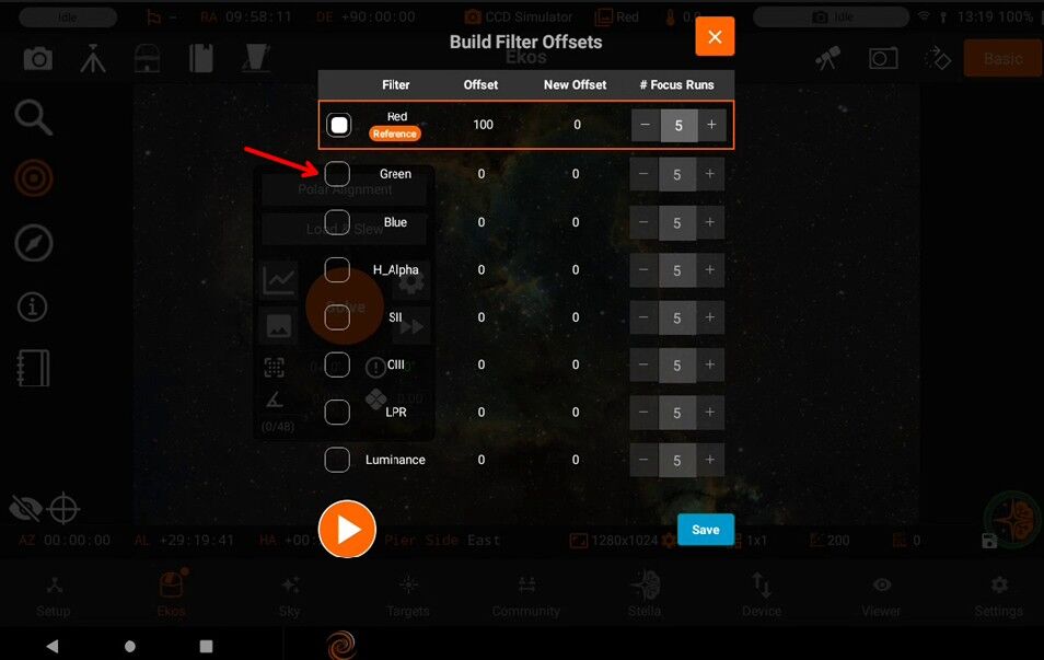
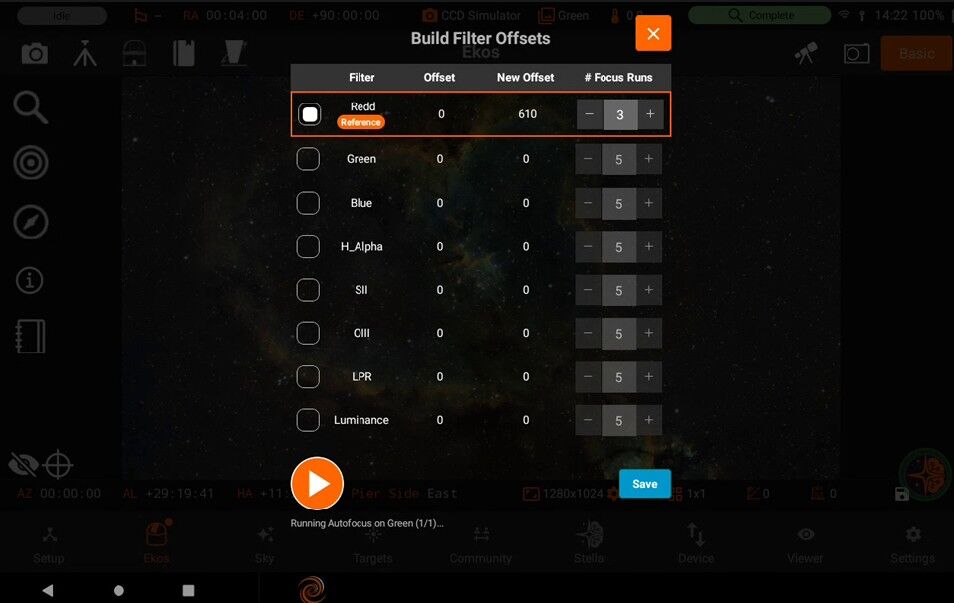
It automates the process of setting up these offsets, rather than requiring you to manually run Autofocus several times per filter, average the results, and calculate the differences yourself. It runs (or uses) focus results across your filters, builds a grid of relative offset values, and lets you review/adjust them — including toggling an Adapt Focus option and changing which filter is used as the reference. (The selected filter is the reference filter)
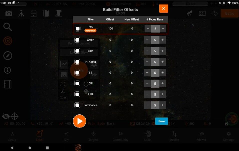
Select the desired filter to change the reference filter
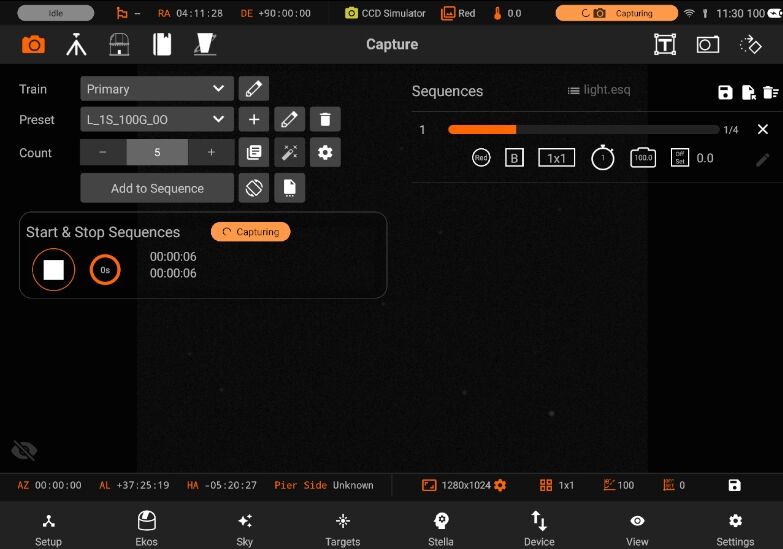
Press the start button to start Progress and wait for the new offset value.
Status Indicator: Displays current camera temperature. Active in all modules except Mount (which has its own status badge).
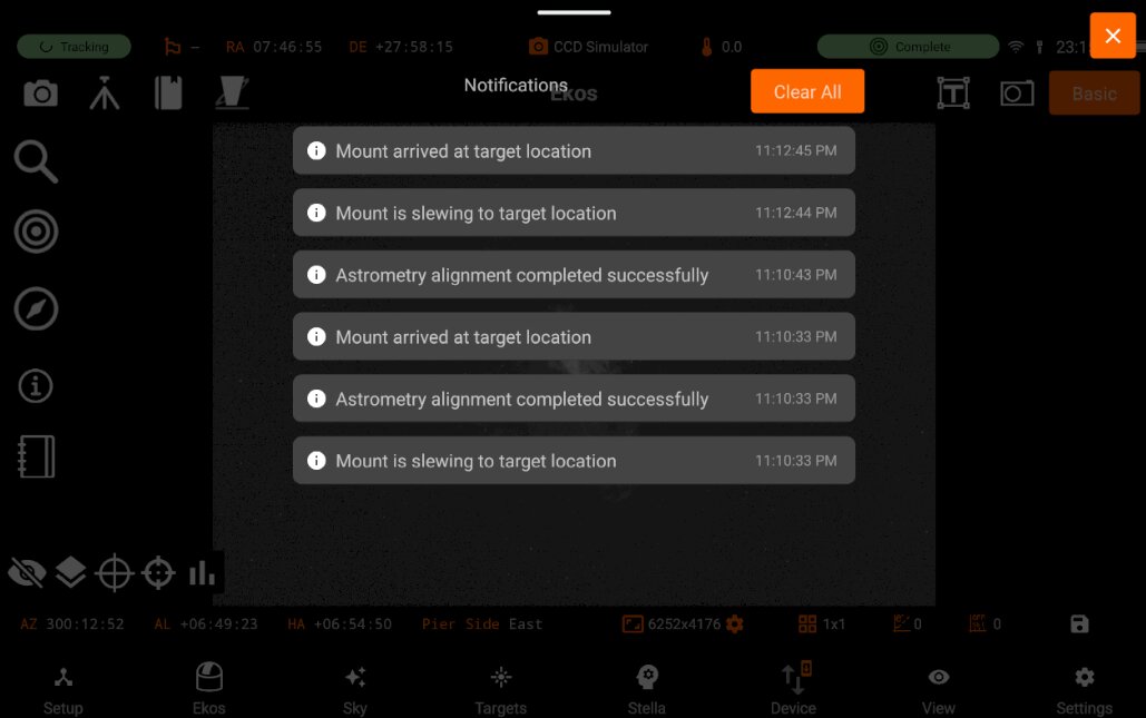
Operation: Tap the temperature status badge to view Notifications History - a chronological list of recent system notifications.
Clear all notifications
View network connectivity status in the status bar: - WiFi Mode: Orange when in hotspot mode and While when in station mode - Ethernet Connected: Shows Ethernet connection status
Battery level Check your device’s current battery level at a glance. The indicator displays remaining power percentage for your mobile/tablet.
5.3.3.2. Bottom
4 - More Mount information:
Correct AZ, AL, HA values Pier Side
5 - More Camera Information
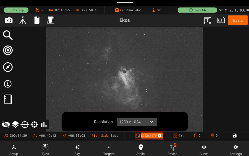
Resolution:
Tap the cog icon to open the Resolution Updater dialog.
Select the desired resolution from the available list.
Binning
Gain
Offset
Save main image
5.3.4. Quick controls
StellarMate App has a total of three Quick Controls Modules which are used to control three astronomical instruments as suggested by their names: mounts/telescopes, cameras, and rotators.
Mount Quick Controls
Camera Quick Controls
Rotator Quick Controls
5.3.4.1. Mount
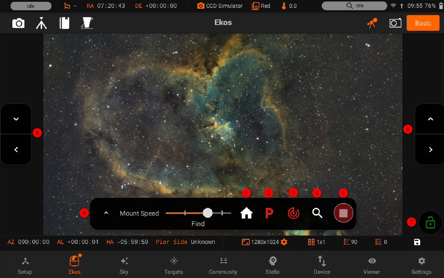
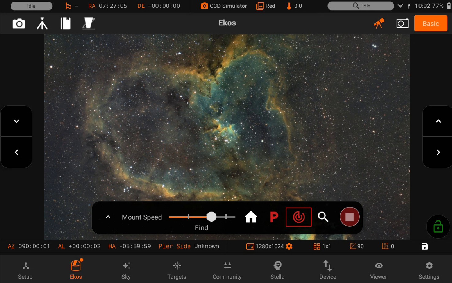
Mount quick controls allows you to control your mount quickly and easily, it has the following features:
Home Support: Toggle Home Support options
Park/Unpark: Park or Unpark mount.
Tracking On/Off: Toggle Mount tracking.
Goto/Sync: Send a GOTO or SYNC command to the mount using a target or a position.
Abort: Immediately abort any mount motion
Mount Speed: Select mount speed when moved via directional keys. Numeric rates (e.g. 600x) usually indicate speed 600 times the sidereal tracking speed. This only affects speeds for manual motion via directional keys and does not change SLEW/GOTO speeds.
Lock Mount Controls: Disable the Mount Controls
- Controls: Buttons from which you can move your Mount
Left/Right/Up/Down: Move your Mount towards specific directions.
Unparking Your Mount
To unpark your mount, tap on the greenbutton, it should turn red signifying that the mount is now UnParked, and the mount status bar shows Idle.
Tracking On/Off
For mount that support tracking control, you can toggle tracking by clicking on button. If tracking is engaged, the icon turns to green and the mount status bar will show Tracking.
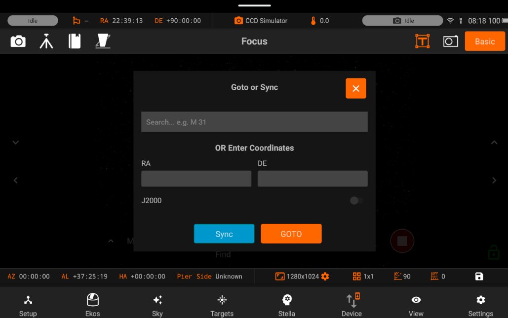
Goto or Sync
You can goto or sync by clicking on the GOTO button, a dialog will pop-up where you can goto or sync to your last target, choose one of your last recently used targets, or select and category and choose a new target.
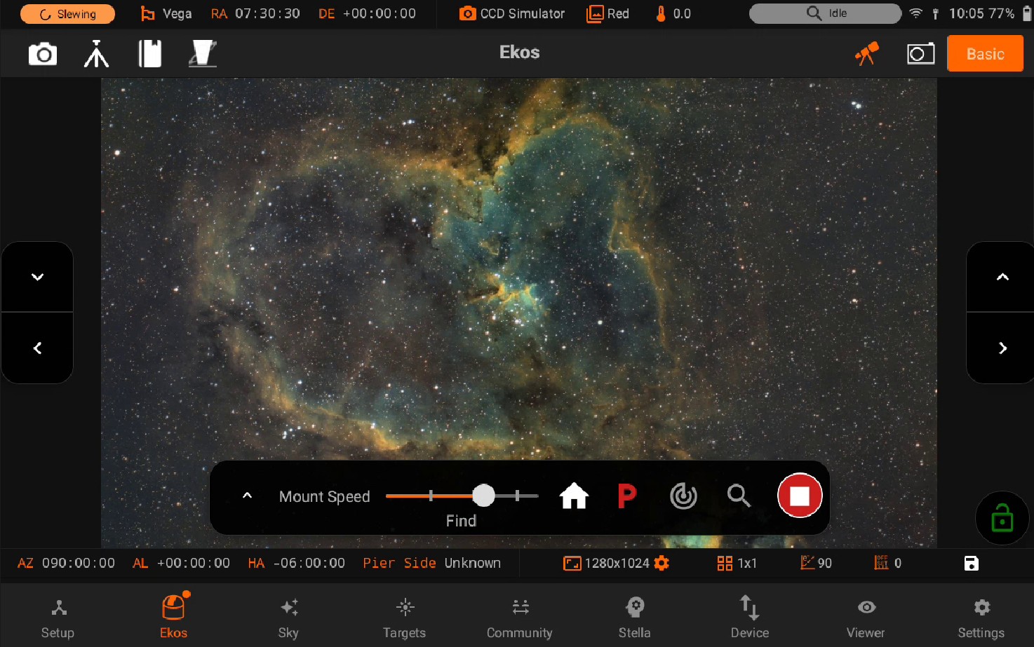
Moving to a specific direction manually
You can move your mount to a specific direction manually by using the Directional pads on the left and right side of the screen.
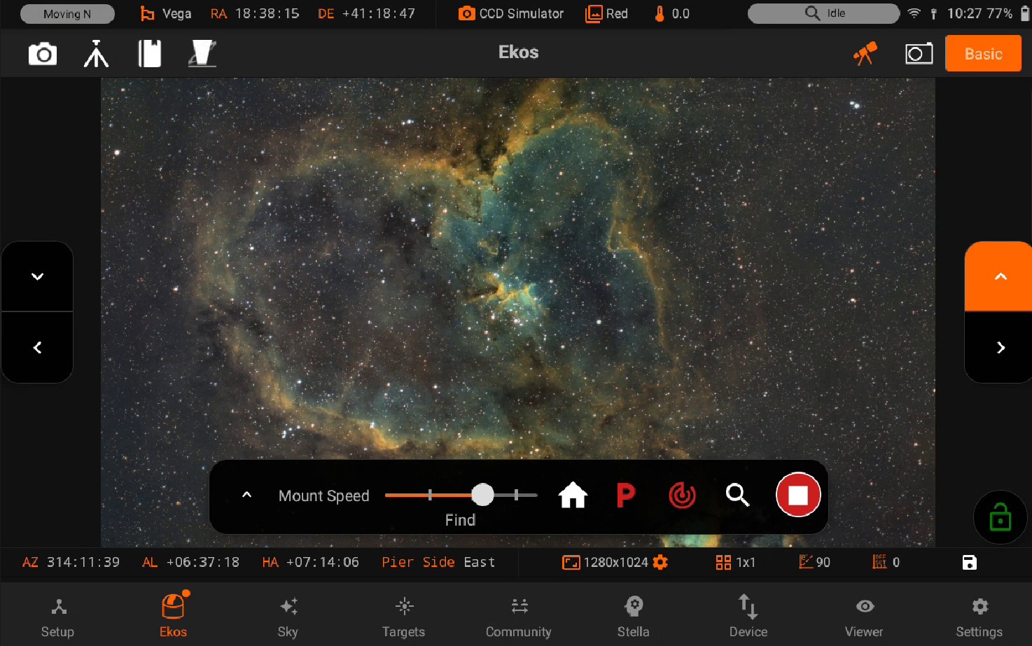
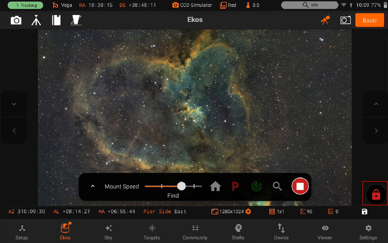
Locking Mount Controls
You can lock mount controls using the Lock button on the bottom-right of the screen. This will disable all the controls, and can be used to avoid any accidental touches.
Parking Your Mount
You can park your mount by clicking on the redbutton, this will turn the button to the yellow color while Parking your mount. After it is done parking, the button will turn to the color green, showing Parked status in the mount status bar.
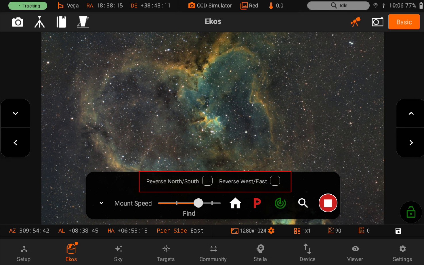
Reverse Directions:
You can reverse the directions of your mount:
North/South: Mount directions will be reversed for North/South when enabled.
West/East: Mouth directions will be reversed for West/East when enabled.
5.3.4.1.1. Home support
Some mounts offer support to slew to a predefined or custom Home position. It is important to clarify the differences between the mount’s Park and Home positions:
Park: Park position is the position the mount should start at when powered on, or stop at before being powered off. A parking position can be fixed by the mount’s firmware or customizable by the user. Usually after a mount is parked, it is expected to be powered off next. Some mounts do not respond to any command when parked.
Home: A home position is the mount’s startup or zero position. For many mounts with relative encoders, the home and park positions are the same. Depending on the mount’s type, the home positions can be different:
Equatorial Mount: Telescope looking at celestial pole with counter weights down.
Alt-Az Mount: Telescope is level with ground looking due North in the Northern hemisphere and South in the Southern hemisphere.
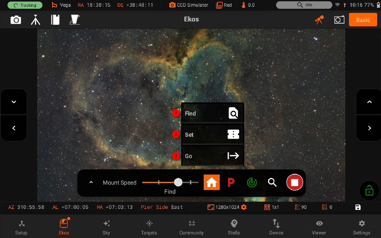
For mounts that support homing, there are usually three operations available in the Mount’s Quick Control bar. Please note that not all mounts support the three operations, some only support a limited subset of these operations:
Find: Search for mount’s home index positions.
Set as current: Save current position as the mount zero position.
Go: Go to mount predefined home position.
5.3.4.2. Camera
Camera quick controls allows you to control your camera quickly and easily. You can quickly change Settings and capture a Preview image, or start a continuous loop Framing until explicitly stopped. Stream and Record videos if supported by your camera. Get amazing pictures with Livestacking
5.3.4.2.1. Preview Framing
Warning
Preview images are not saved in Internal Storage
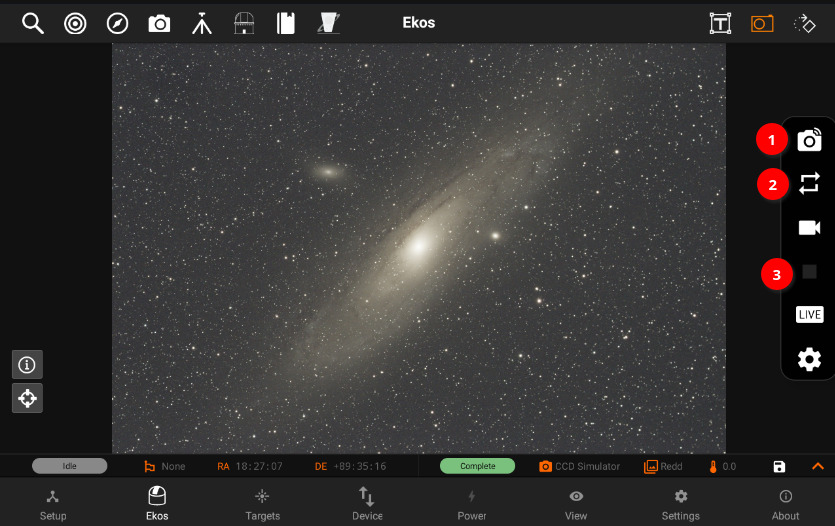
- You can capture a preview image by tapping on the Camera button.
An animated circular progress icon will show the progress of the current capture and will show you when the image is being downloaded to the app by showing a green cloud download icon.
Looping can be done as well by tapping on the Loop button (repeat icon).
You can stop the capturing process by tapping on the Stop button anytime while it’s capturing.
5.3.4.2.2. Video Recording
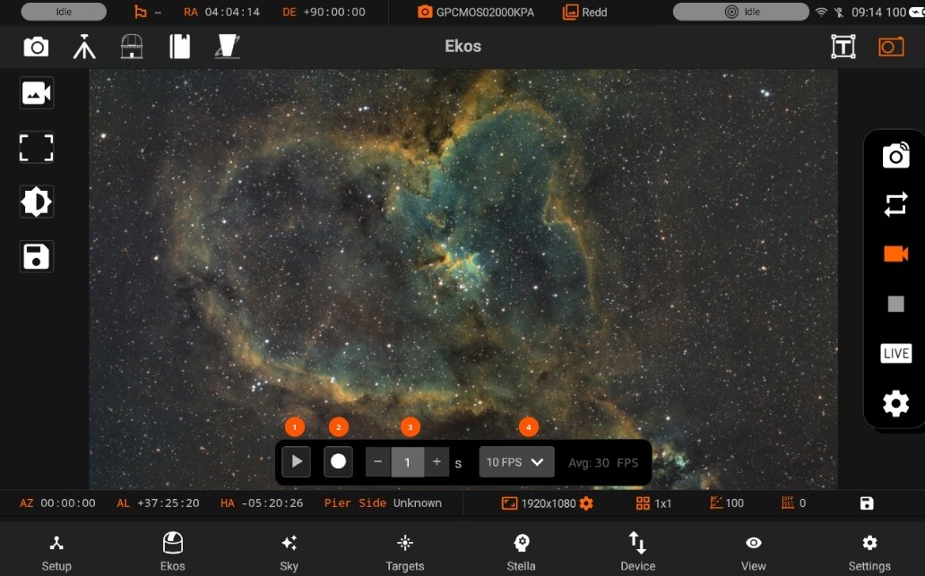
Videos are recorded as lossless SER format. By default, they are saved to the StellarMate Videos directly which can be accessed via Network share on Windows, Mac, and Linux.
These are the following options in Video Recording:
Play: Enables the video streaming if supported by the camera.
Record / Stop: Starts the recording, if the recording is started. Icon will be changed to stop icon. So, you can stop the recording.
Duration: Select one from the predefined video duration.
Avg FPS: Average running Frame per second
Streaming
Once you starting video streaming, a box is shown on the screen. You can resize it using the resize button from the bottom right. Live histogram view is also shown.
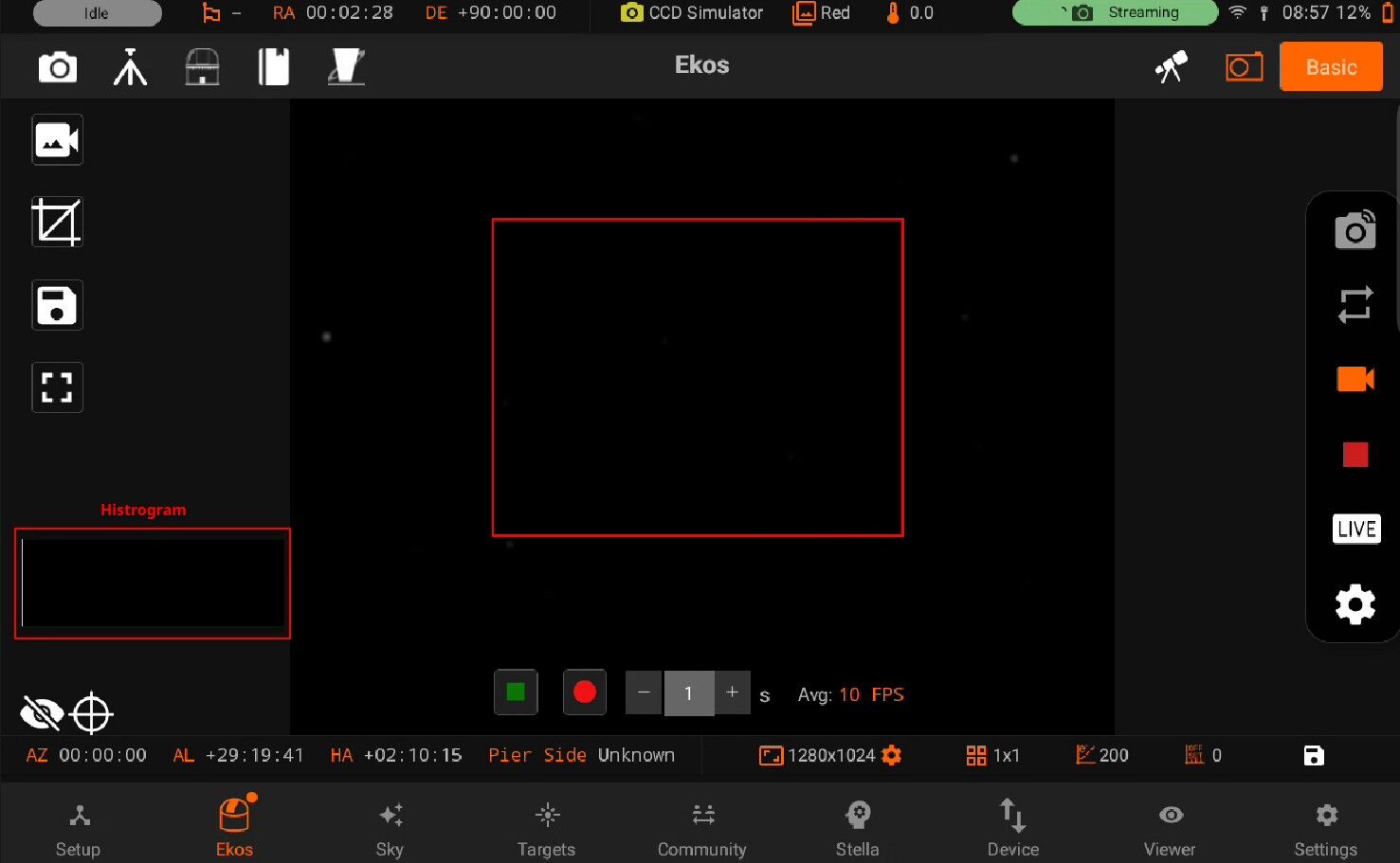
Once resize, you can also drag the box. Double tap on the box to set the Streaming ROI frame values.
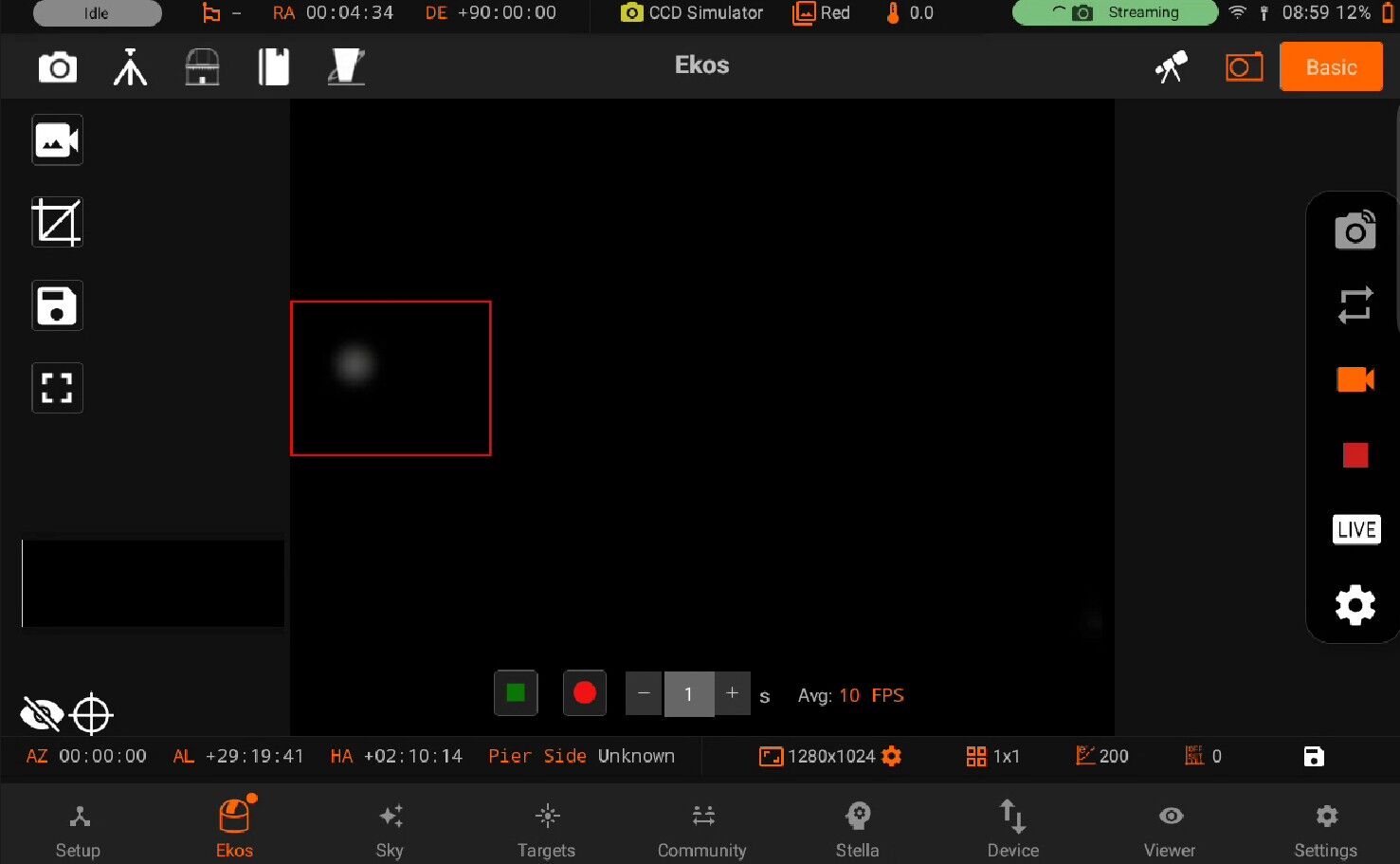
Binning: Horizontal and Vertical binning
Left: Specifies the area of x position i.e Horizontal
Top: Specifies y position i.e Vertical
Width: Current width of Active camera
Height: Current height of Action camera
Settings: Directory and filename settings
Press outside the box to reset the Streaming frame.
5.3.4.2.2.1. Canvas
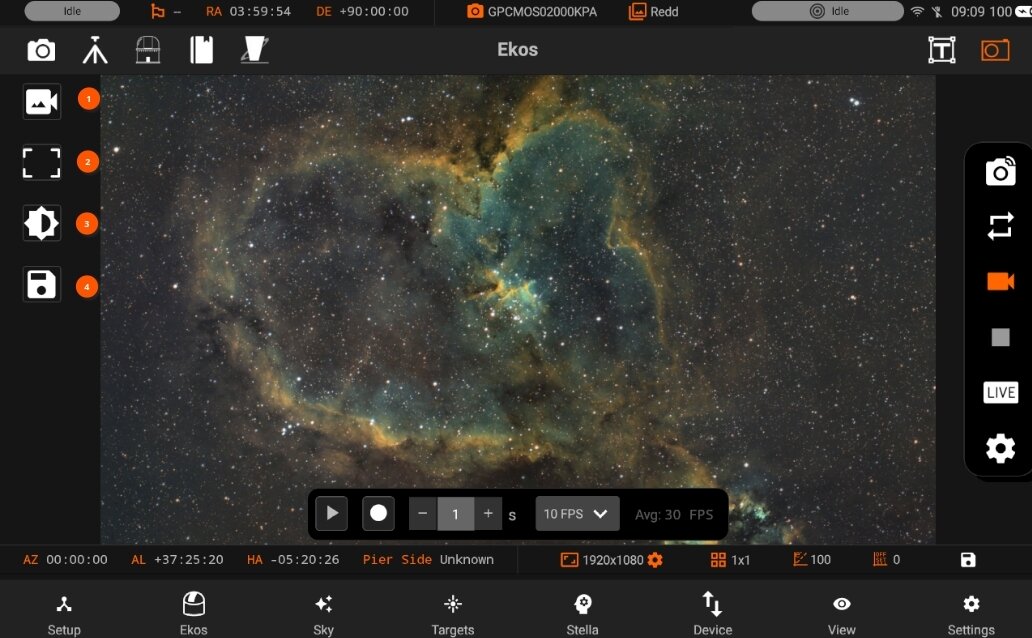
On the left side, you can see Video adjustment controls:
Exposure/Gain controls
ROI Frames
Camera adjustments
File saving
5.3.4.2.2.2. Exposure/Gain
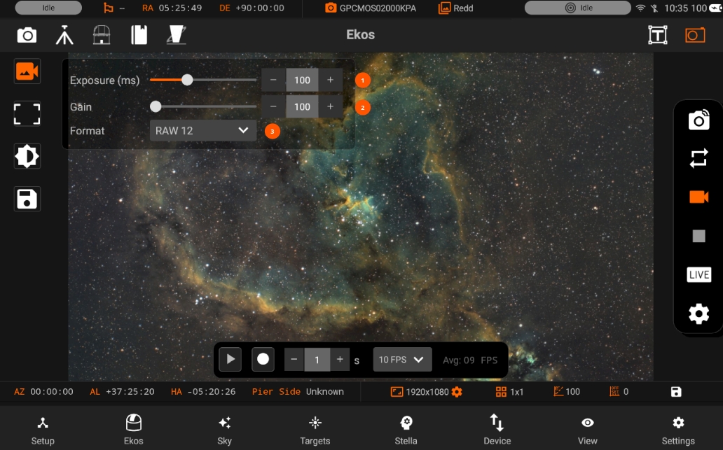
Adjust Exposure, Once it is changed Streaming will automatically restart. Adjust Gain value. Select format of the Stream
5.3.4.2.2.3. ROI Frames
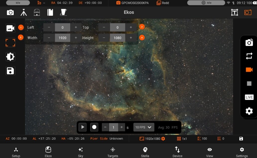
Region of Interest: Specify the video frame. By default, a full frame is captured. All units in pixels
Left: Left offset
Top: Top offset
Width: Width (unbinned)
Height: Height (unbinned)
Left+Width should not exceed the maximum width of the camera. The same rule applies to Top+Height.
5.3.4.2.2.4. Adjustments
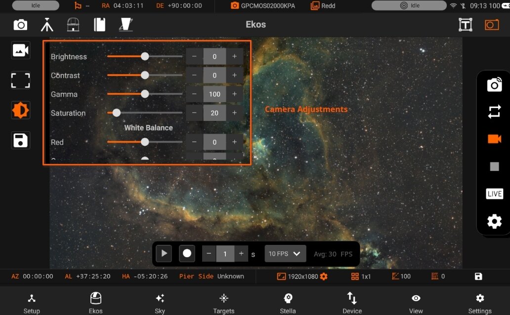
Adjust Camera controls with the live histogram view when the Live Streaming is in progress
5.3.4.2.2.5. File save
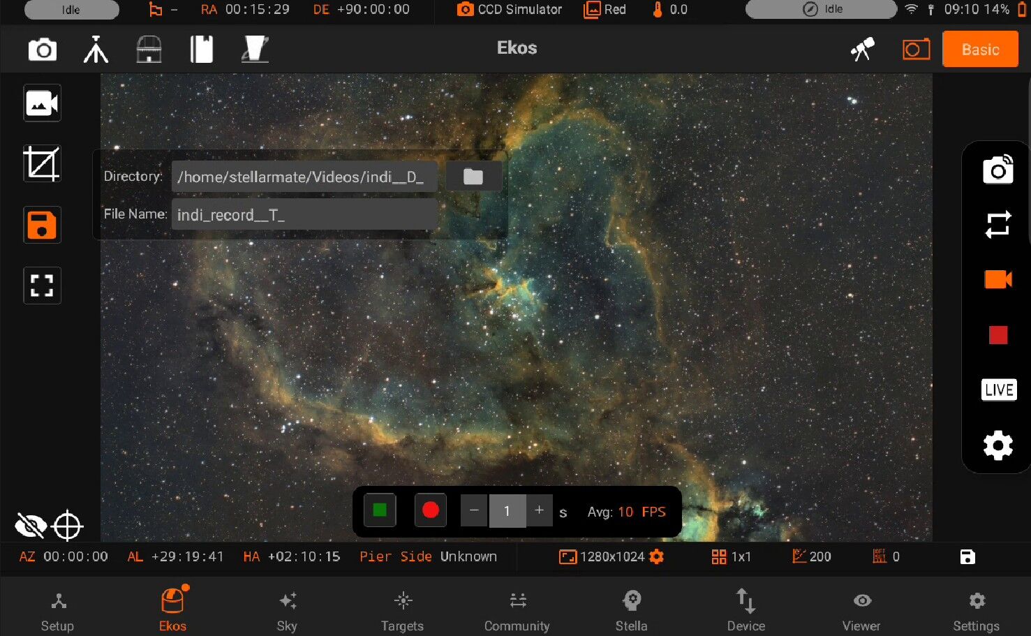
Directory: Path of videos is set using Directory browser.
- File NameSet SER video file name. Record files may contain some patterns to make them dynamic.
_D_: For the date in YYYY-MM-DD
_H_: For time in HH:MM:SS.
_T_: For ISO8601 time stamp.
_F_: For filter name, if any.
Directory: Path of videos is set using Directory browser.
Toggle Directory browser
File Name: Set SER video file name. Record files may contain some patterns to make them dynamic.
_D_: For the date in YYYY-MM-DD_H_: For time in HH:MM:SS._T_: For ISO8601 time stamp._F_: For filter name, if any.
Offset: Target camera offset
Gain: Target camera gain
Videos are recorded as lossless SER format. By default, they are saved to the StellarMate Videos directly which can be accessed via Network share on Windows, Mac, and Linux.
5.3.4.2.3. Live Stacking
Live Stacking is a powerful Electronic Assisted Astronomy (EAA) feature in the StellarMate App that combines incoming frames in real time to boost the Signal-to-Noise Ratio (SNR) of your image. It is based on the powerful Ekos LiveStacker. As each new sub-frame is captured and stacked, noise is progressively reduced and the contrast of deep-sky objects improves. Galaxies, nebulae, and star clusters begin to emerge within minutes without any post-processing.
Prerequisites Before starting Live Stacking, the following conditions must be met:
Plate Solve first. Live Stacking depends entirely on plate solving to align frames. Each incoming sub-frame must carry valid WCS (World Coordinate System) data embedded in its FITS header. Make sure the Alignment module has completed a successful solve before engaging the livestacker. Without it, frame registration will fail.
The image must be well-focused. Poor focus reduces the number and quality of detected stars, which the alignment algorithm relies on. Run autofocus before starting your session.
Sufficient stars must be present in the frame. The stacking algorithm detects stars in each captured sub to compute the registration transform. Very sparse star fields or extremely narrow-band targets may reduce alignment reliability.
Guide for exposures longer than 30 seconds. Most consumer-grade mounts begin forming star trails beyond 30 seconds. For longer exposures, activate guiding before starting the livestacker. Good polar alignment significantly improves results at all exposure lengths.
Starting Live Stacking
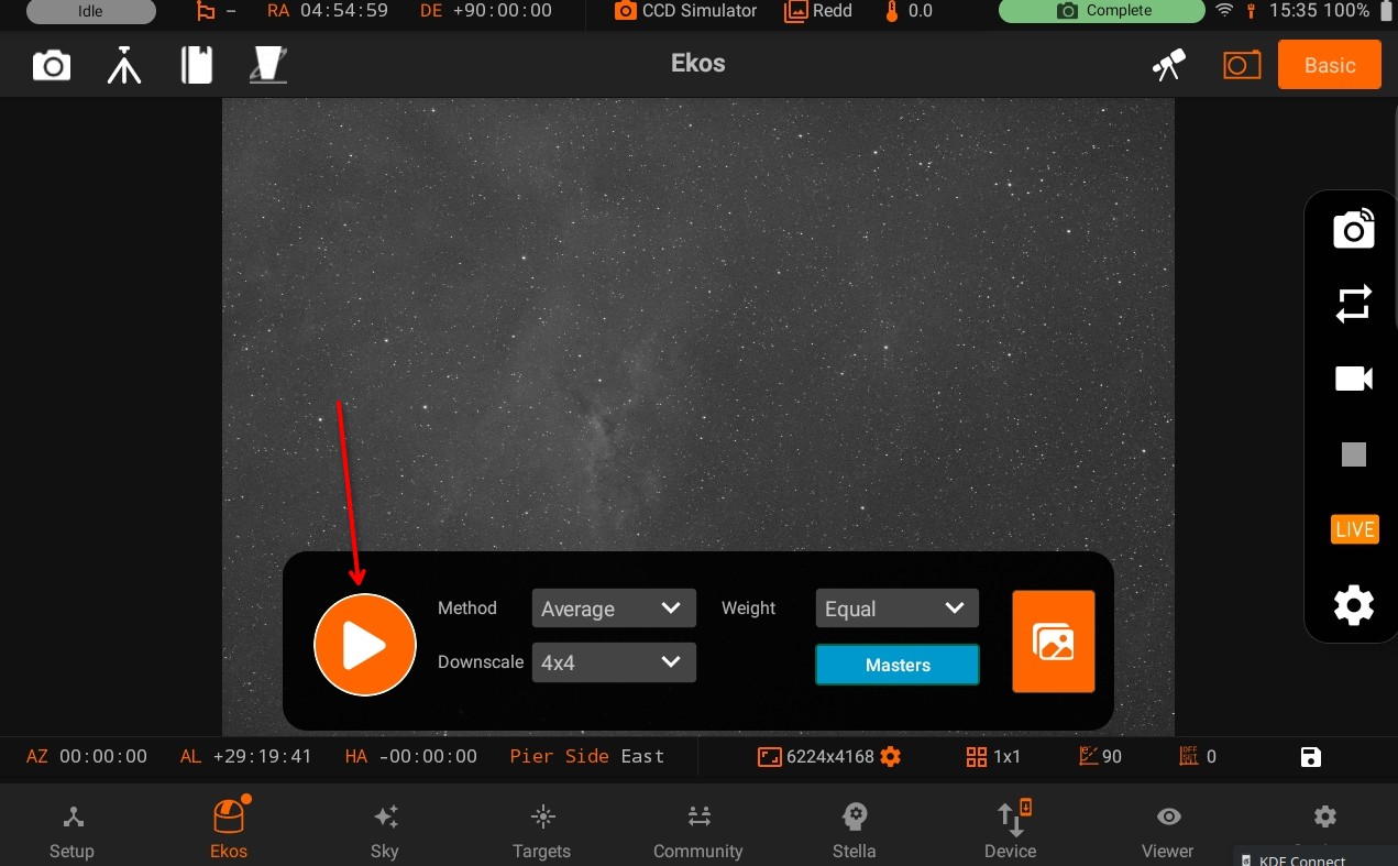
Tap the LIVE button in the Camera Quick Controls to access the Live Stacking panel, then tap Play to begin.
Without a running sequence: If no capture sequence is active, the livestacker starts an automatic capture loop using the primary camera settings from Quick Controls. For example, if your exposure is set to 5 seconds, a 5-second loop runs continuously until you stop it.
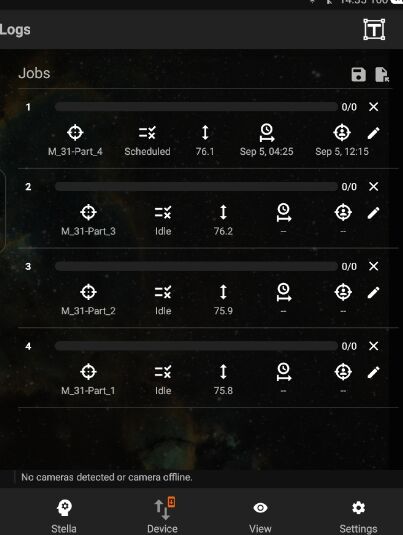
With a running sequence: If a sequence queue is already running, enabling the livestacker causes it to wait for the next arriving frame and stack it as part of the ongoing sequence.
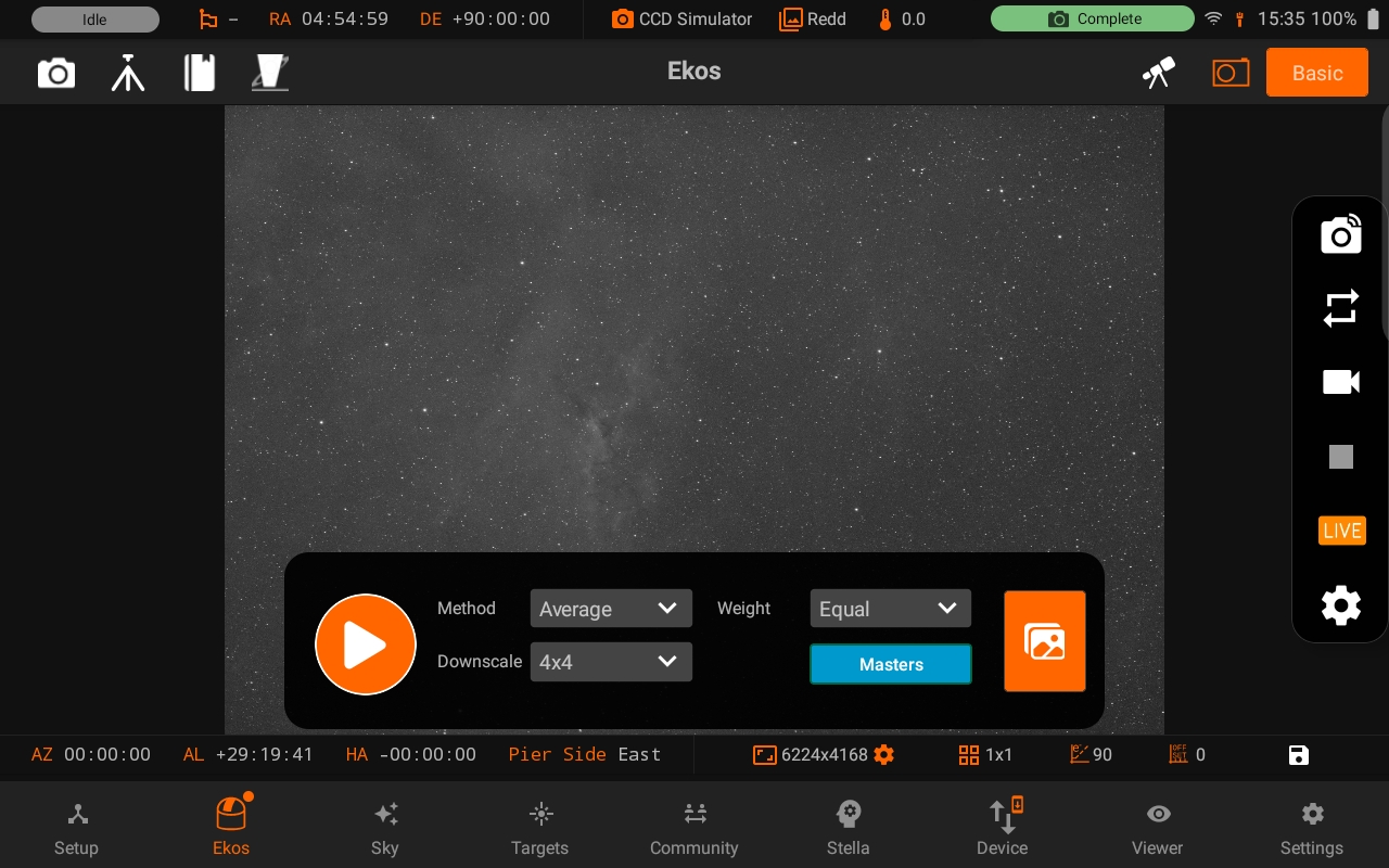
In both cases, the first captured frame is used to extract the reference star pattern and establish the WCS reference. Actual stacking begins from the second frame onward.
Viewing Stacked Images
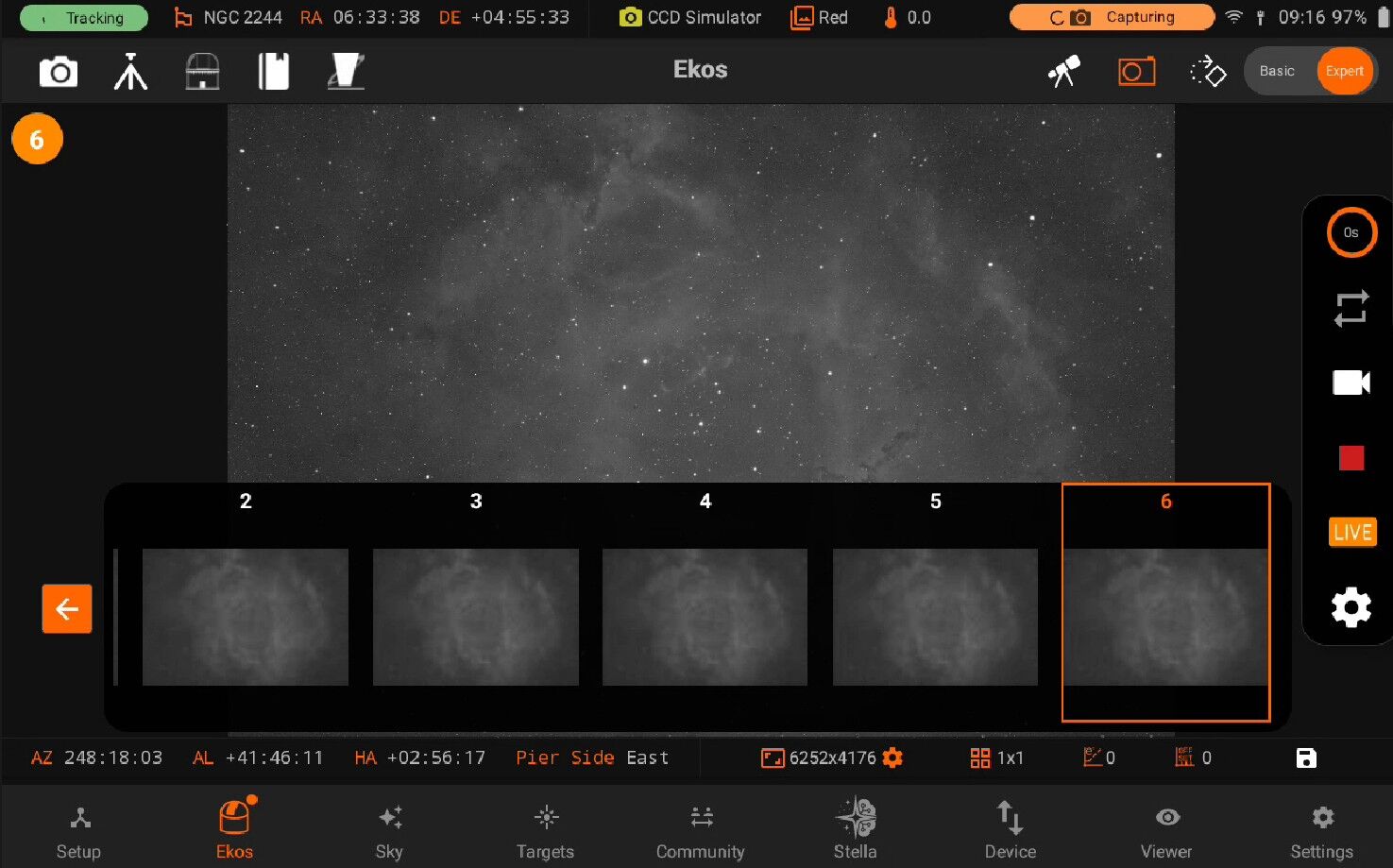
As stacked images arrive, they are displayed in the main view. A thumbnail carousel at the bottom of the screen shows the last 10 captured frames, numbered sequentially. Tap any thumbnail to view that specific frame. When the livestacker is restarted, all images are cleared and the carousel resets.
Stacking Settings
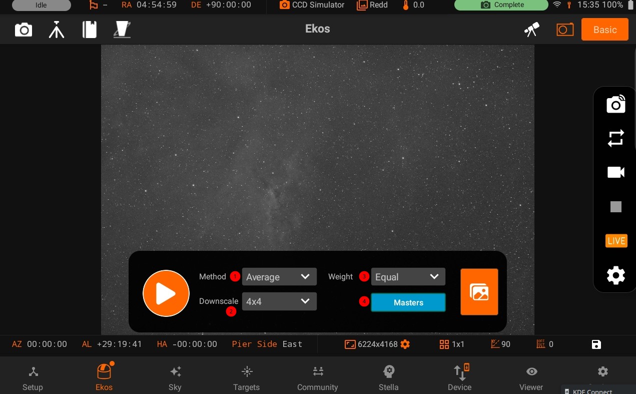
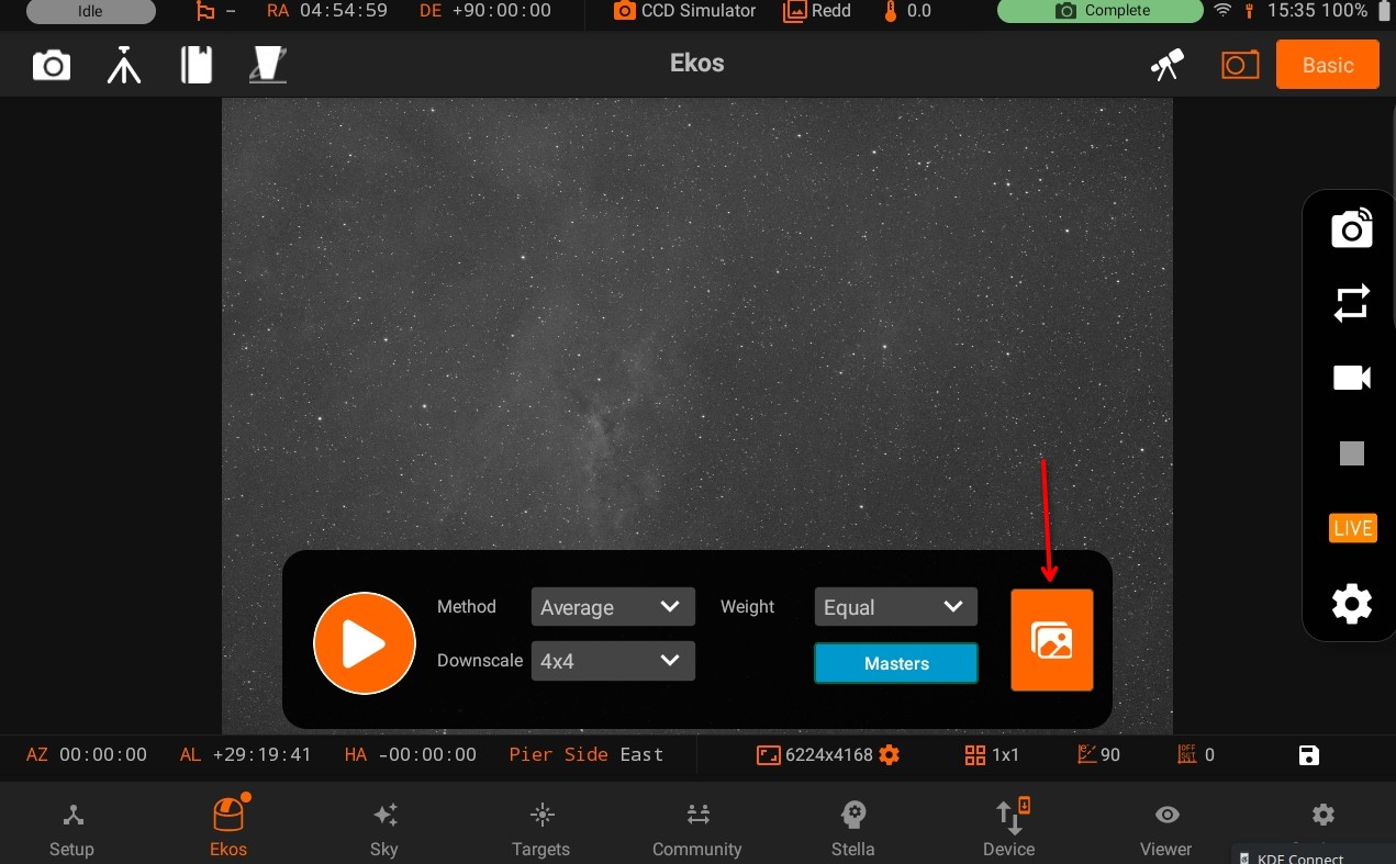
1. Stacking Method Controls how pixel values are combined across frames:
Average: Simple mean of all pixel values. No rejection is applied. Fast and straightforward, best for clean conditions.
Sigma Clipping: Rejects outlying pixels that deviate beyond a statistical threshold. Helps suppress hot pixels, cosmic rays, and satellite trails.
Winsorized Sigma Clipping: A more robust variant of sigma clipping that limits, rather than removes, outlying pixel values. Better behavior with small frame counts.
ImageMM: Implements the ImageMM stacking algorithm as described in this astronomical paper. Produces excellent results for faint targets but is significantly more resource-intensive than other methods. Use with caution on lower-powered hardware.
When Live stacked images are received, they are displayed in the main view with a thumbnail carousel at the bottom. Each image is numbered sequentially. To ensure proper performance, only the last 10 captured images are available in the carousel. To view a specific image, simply tap its thumbnail in the carousel. When the livestacking is restarted again, all images would be cleared.
2. Downscale Reduces the resolution of sub-frames and the master stack before processing. Useful for improving performance on resource-constrained devices or when real-time speed is more important than full resolution:
None: Full resolution, no downscaling.
2×2: Subs and master stack downscaled by a factor of 2.
3×3: Downscaled by a factor of 3.
4×4: Downscaled by a factor of 4.
3. Frame Weighting Determines how much influence each frame has in the final stack:
Equal: All frames contribute equally regardless of quality.
HFR: Frames are weighted by 1 / Average HFR (Half-Flux Radius). Sharper frames with smaller HFR carry more weight.
Num Stars: Frames are weighted by the number of detected stars. Frames with more detected stars are considered higher quality and weighted accordingly.
4.Calibration Masters Optional calibration frames to improve image quality:
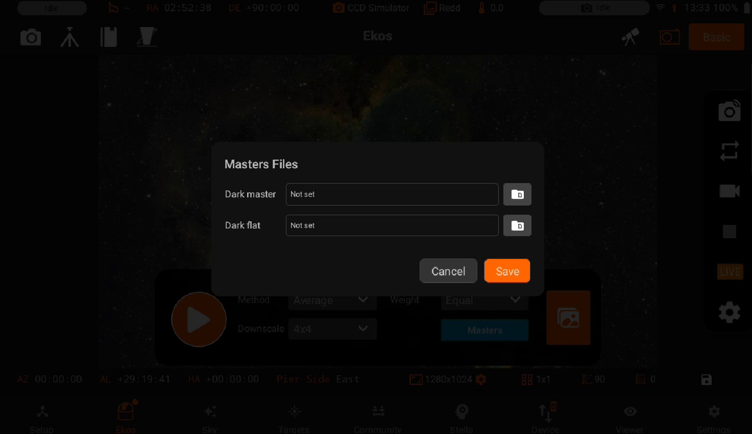
Master Dark: Select a master dark frame to subtract thermal noise and hot pixels from each incoming light frame.
Master Flat: Select a master flat frame to correct for optical vignetting and sensor dust.
Both masters should be matched to your camera settings (gain, temperature, binning) for best results.
Saving Stacked Images Live stacked images are saved as FITS files in the StellarMate Pictures directory. They retain full 16-bit or 32-bit data fidelity and include WCS header information, making them suitable for further processing in PixInsight, Siril, or other astrophotography tools. Saved images can be accessed later via the Gallery, StellarMate network share, or FTP.
Warning
Previous versions of the StellarMate App saved stacked images as JPG. The current system saves in FITS format to preserve full data quality.
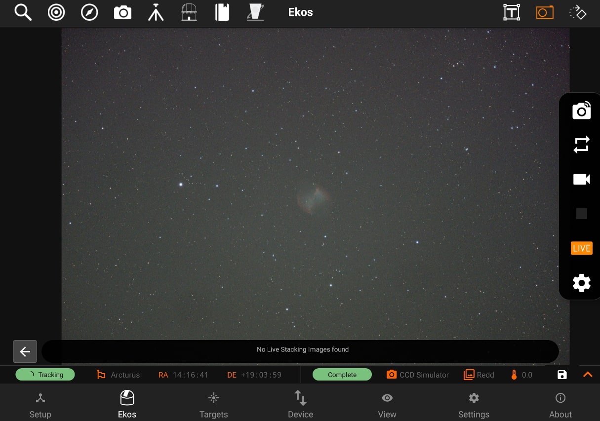
All live stacked images are saved as JPG in StellarMate Pictures directory, where they can be accessed later via the Gallery, StellarMate network share, or FTP.
To save an image in the tablet/phone storage, tab the Disk icon in the camera’s info bar.
5.3.4.2.4. Settings
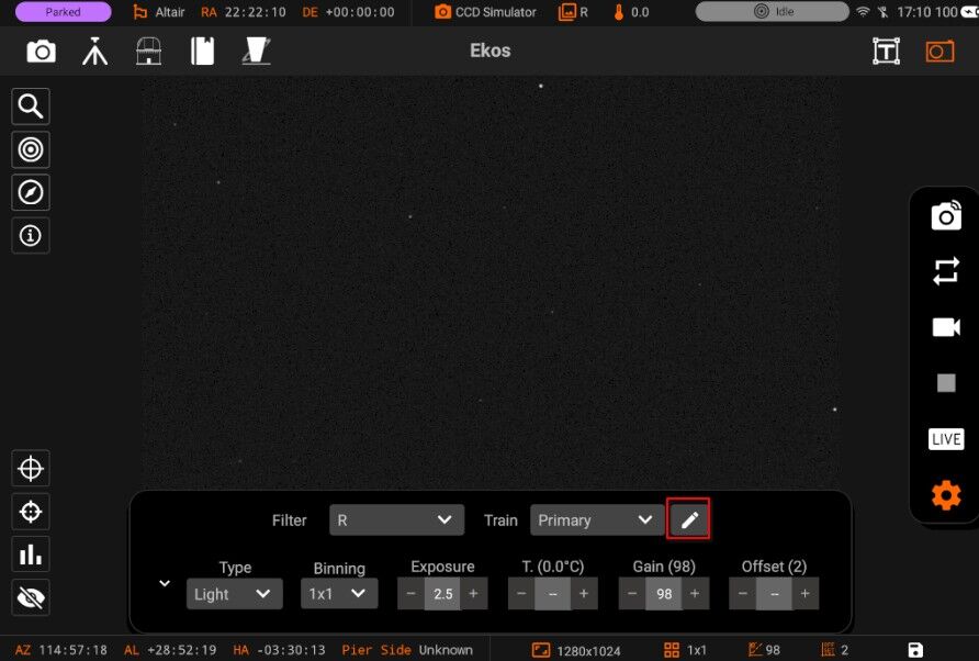
You can quickly take custom preview captures or loop frames by tweaking the settings in the quick settings bar by tapping on the Quick Settings button. The quick settings bar can be expanded by tapping on the up expand arrow on the left side of the bar. Different settings can be changed for a specific camera i.e Frame type, Binning, Exposure, Temperature, Gain & Offset.
Note: Choosing a temperature will set the temperature immediately.
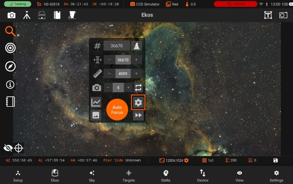
You can also toggle Optical trains from the Quick Camera Settings
5.3.4.3. Rotator
Rotator quick controls allows you to control your rotator quickly and easily, it has the following features:
- Display Current Angle (please note all angles are in degrees)
Goto absolute angle 10-step Counter-Clock-Wise Movement 10-step Clock-Wise Movement Abort Motion
Going to absolute angle
You can go to an absolute angle by tapping on the textbox and typing it the angle you want to go to, then tap on the Goto button next to the text-box on the right. You will be able to see the angle display view changing along the way to its final angle.
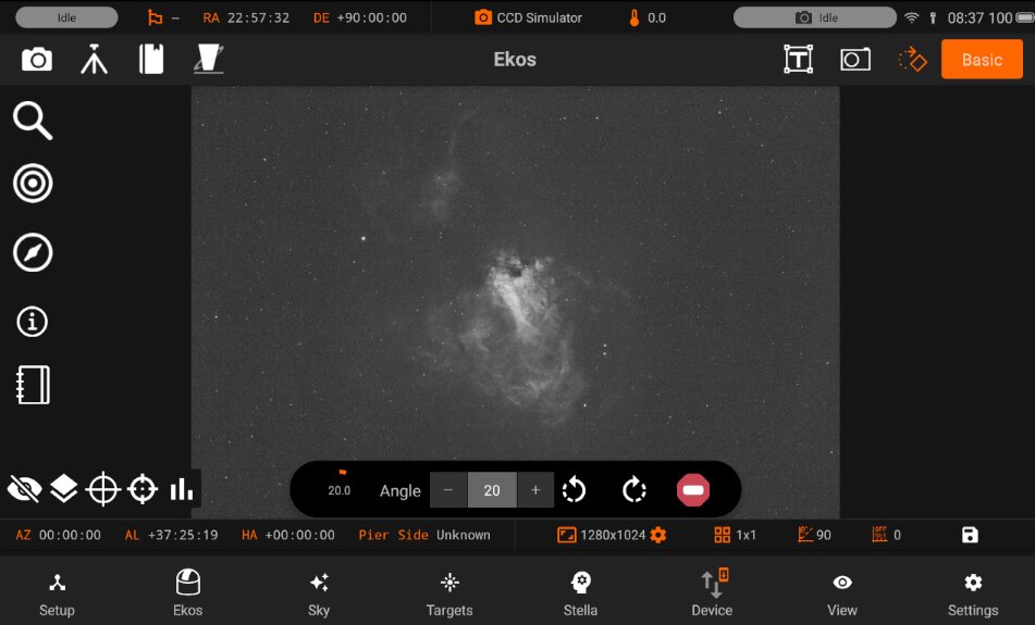
Going to an angle position by steps
You can rotate the rotator to a different angle using the CW and CCW rotation buttons, which will change the rotation by 10 steps depending on the direction chosen.
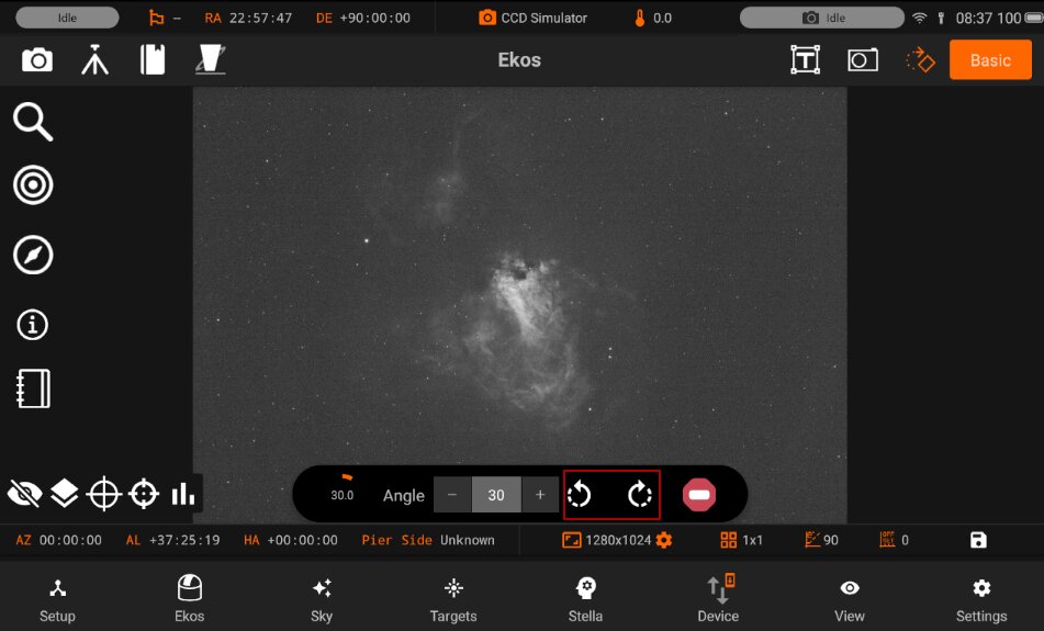
5.3.5. Modules
Advanced controls for Focusing, Guiding, Alignment, Capture, Mount, Observatory, Scheduler, and INDI Control Panel.
StellarMate App has a total of six Ekos Modules which are used to control various astronomical instruments such as: CCD cameras, DSLR cameras, mounts/telescopes, dustcaps, domes, roll-off shutters, filter wheels, rotators, focusers, and more.
5.3.5.1. Align
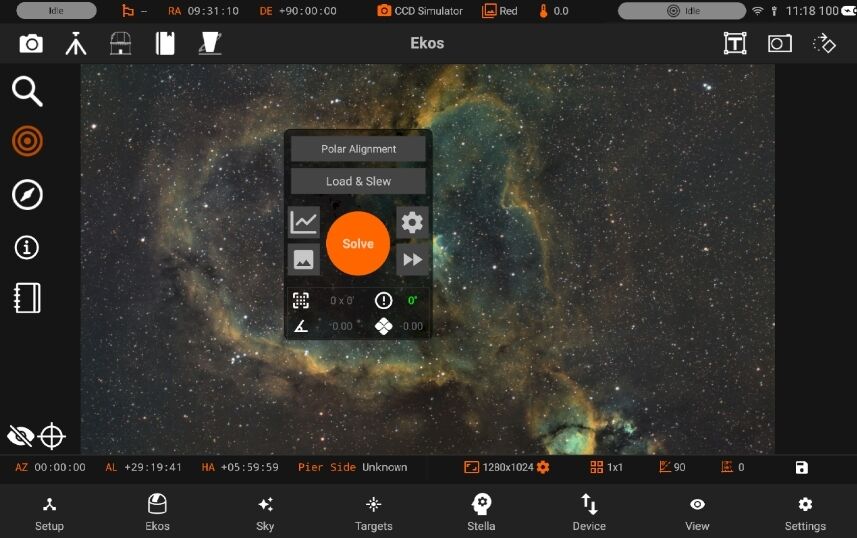
The Align module enables highly accurate GOTOs and dead-center target images by utilizing plate-solving. The process starts with capturing an image and plate-solving it to get the exact sky coordinates. Once the coordinates are obtained, the mount is synchronized and then commanded to slew to the correct target position. This cycle repeats until the mount is within a few arcsecs from the target.
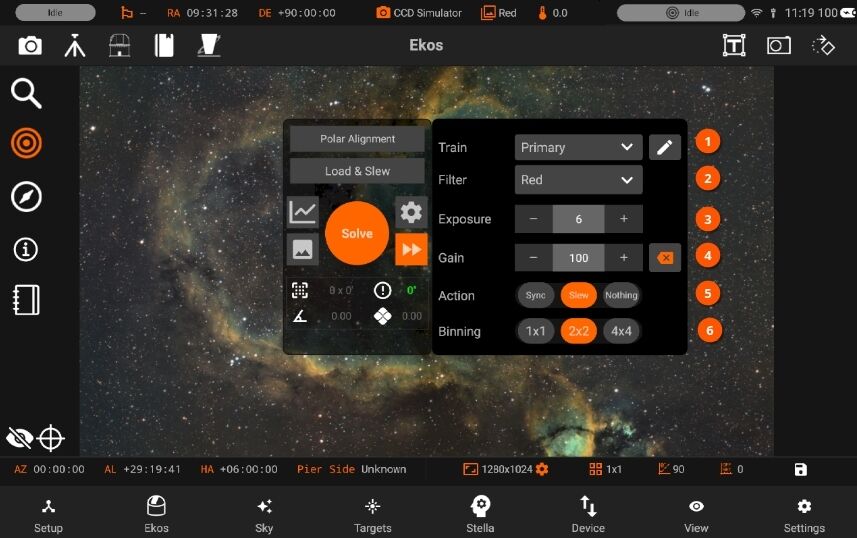
It has the following features:
Manage / Select Optical trains.
Filter
Exposure
Gain
Action: Sync, Slew to target or do nothing.
Binning
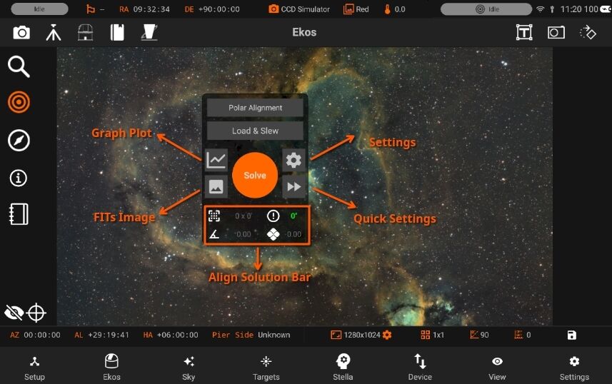
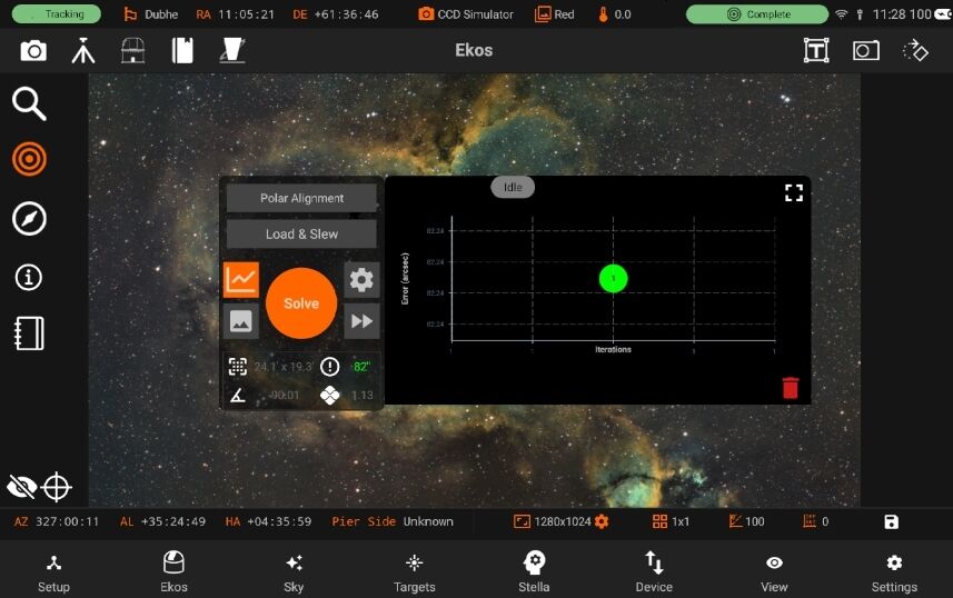
Graph Plot: Displays the alignment graph when the image has been plate-solved.
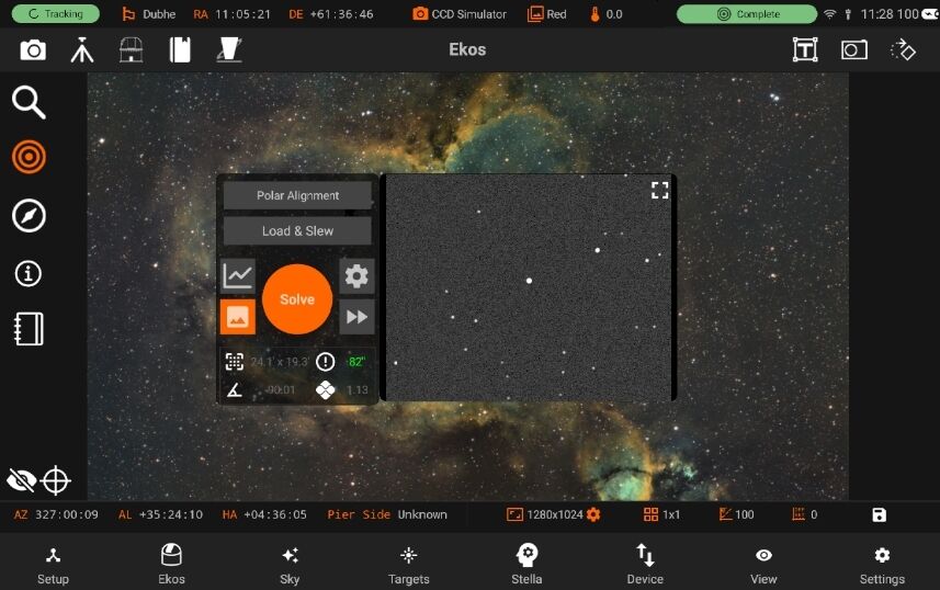
FiTs Image: Displays the most recent aligned image.
Settings: Opens the alignment settings menu. Quick Settings: Provides a quick method to modify the settings.
Solution Bar: Displays information such as field of view (FOV), position angle, error, and other details when the image has been plate-solved.
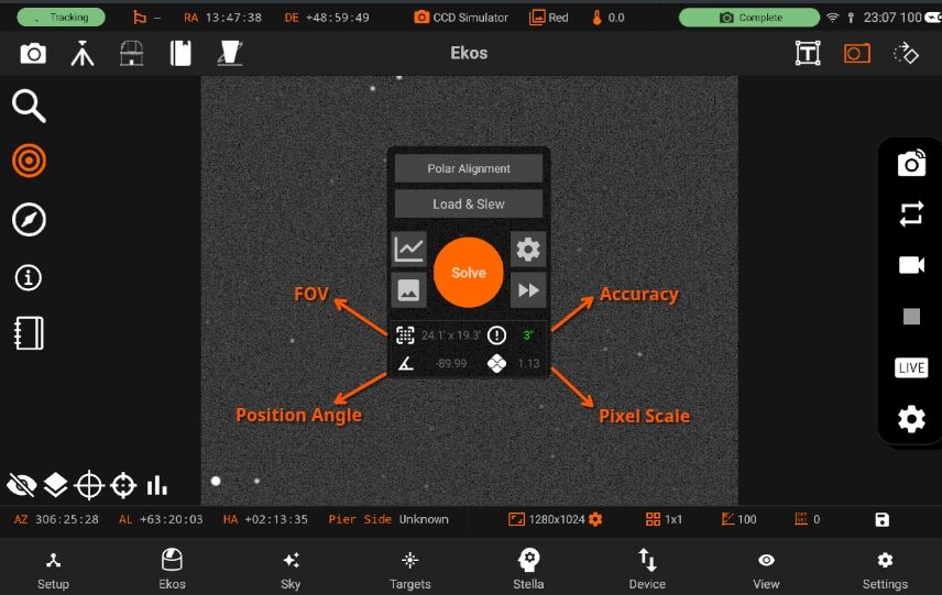
FOV: Effective field of view in arc-minutes. * Position Angle: Image Rotator angle, East of north. * Accuracy: Difference between target and solution coordinates in arcsecs. * Pixel Scale: Image pixel scale in arcsecs/pixel
Capture & Solve
To start capturing and solving, just tap on the Capture & Solve button and the StellarMate will take care of the rest. When it’s done, you will be able to see the current Alignment capture preview, alignment info on the solution bar on the bottom, and the points on the Alignment plot.
Load and Slew
It is used to command the mount to the center of the uploaded image. First, the provided image is plate-solved and then the mount is commanded to slew to the target. Afterwards, a second plate-solve with the camera takes place to ensure the mount is in the correct spot.
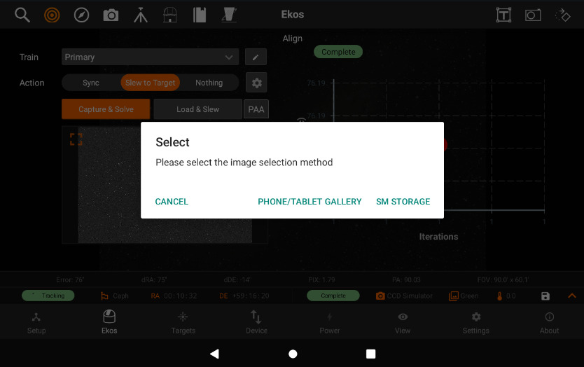
You can load Fits file from the tablet or using Directory browser to access SM device files. To start a load and slew action by tapping “Phone/Tablet Gallery” and selecting an image to slew to. Stellar-solver is very accurate at this and will be able to slew to object in the image.
Astronomy Index Files:
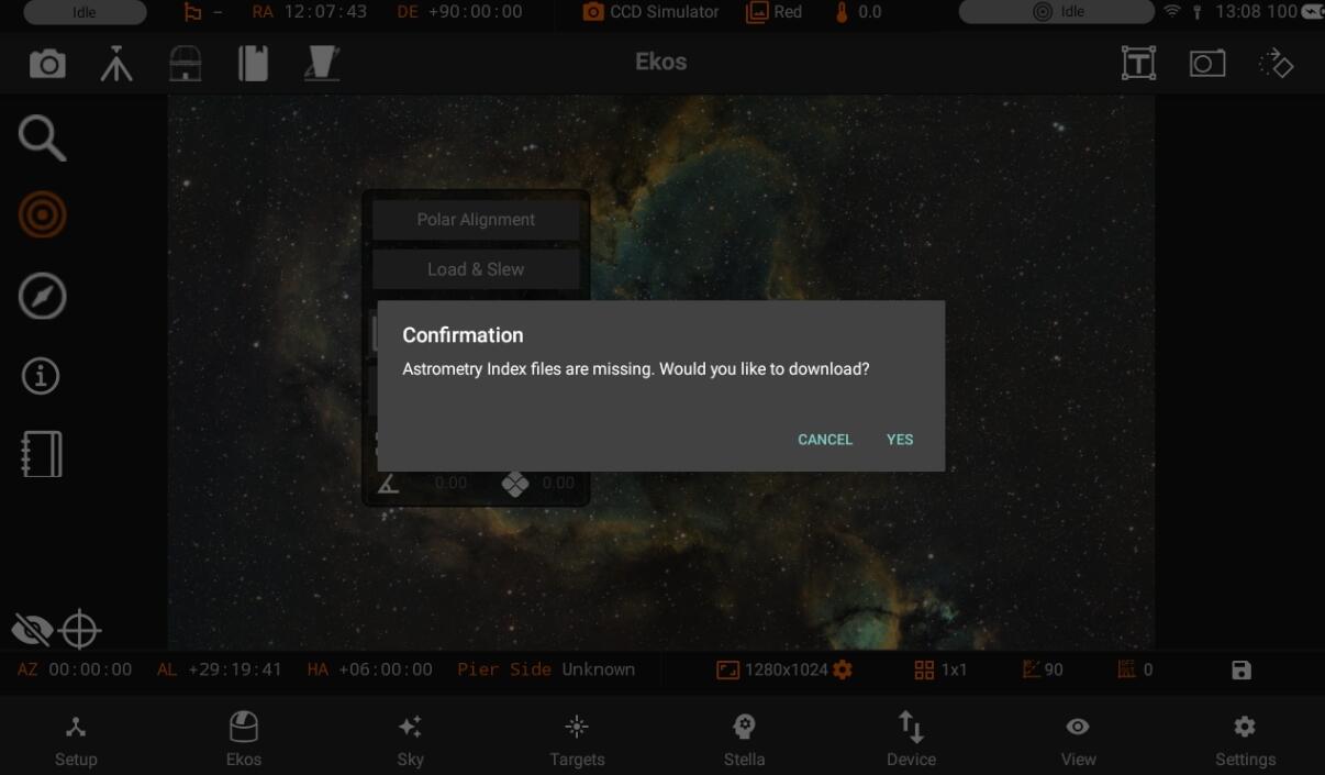
If index files are missing, a pop-up notification will prompt the user to decide whether to download the required files.
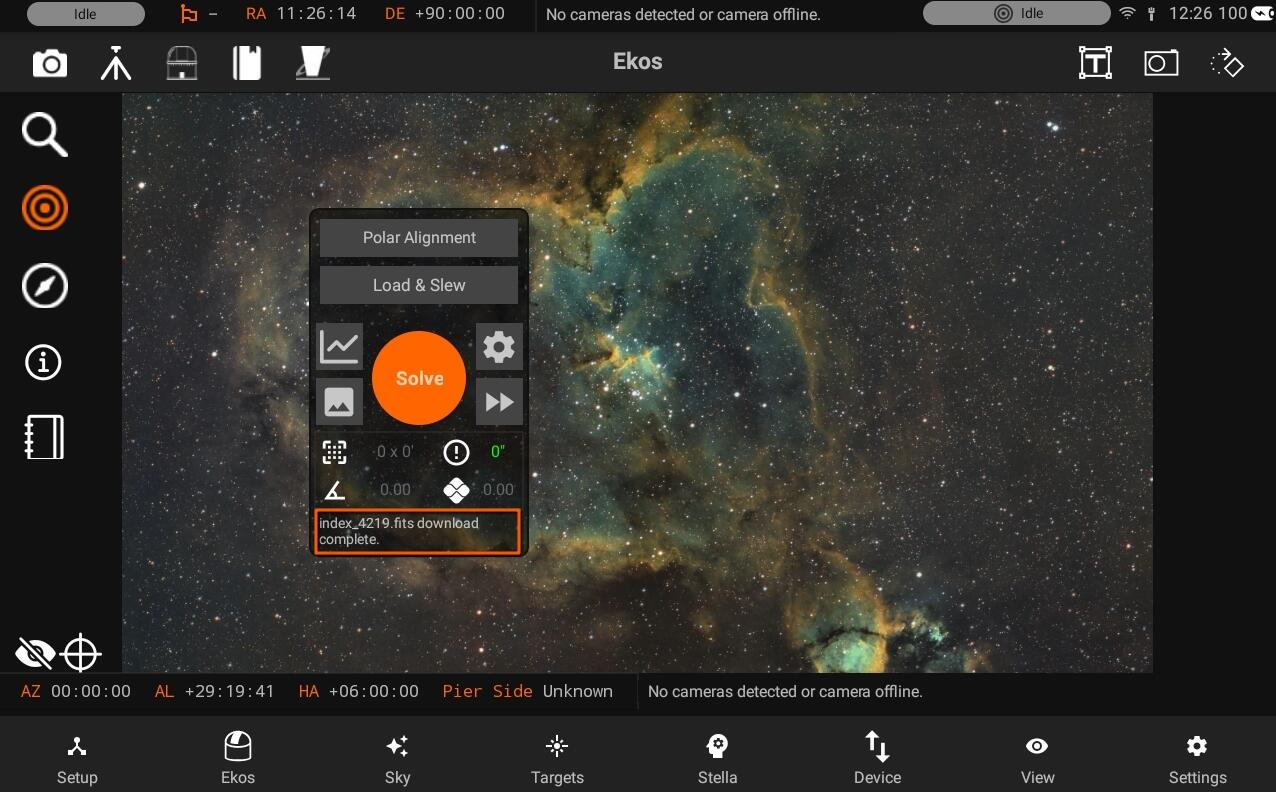
Below, the interface displays the status of the download progress to keep the user informed.
5.3.5.1.1. PAA
Polar Alignment Assistance (PAA)
If your mount supports Polar Alignment, you can use the Polar Alignment Assistant (PAA) to improve your alignment.
The key is that you need a clear view of some stars, but they don’t specifically need to be Polaris. The tool will analyze the star’s movement pattern to determine the alignment corrections needed.
However, for best results:
Choose a star that’s relatively high in the sky (around 30-60 degrees altitude) Make sure your mount is roughly aligned (within several degrees) Ensure your mount is level Use a star that isn’t too close to the meridian (To prevent a meridian flip)
To start the polar alignment process, open the polar alignment assistance by clicking on PAA button.
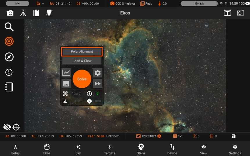
Use the Polar Alignment Settings to modify the settings.
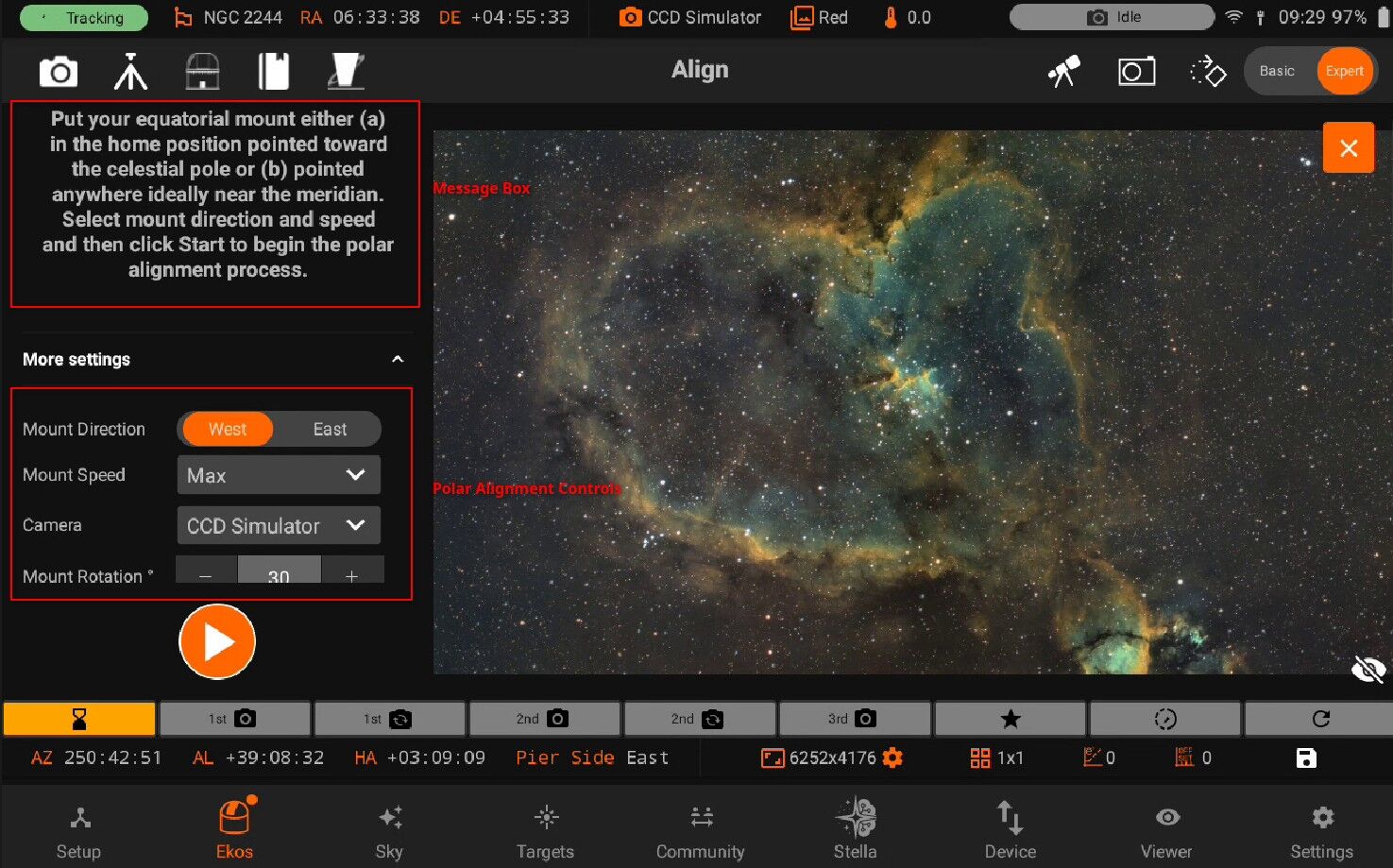
You can adjust the mount direction (1) by selecting West or East rotation. Adjusting the Mount Speed (2) by opening the speed menu and selecting the preferred rotation speed. Mount Rotation (3) allows the user to modify the amount of rotation the mount rotates after every capture. Manual Slew (4), the option to allow the user to manually rotate the mount after every capture and continue the process manually.
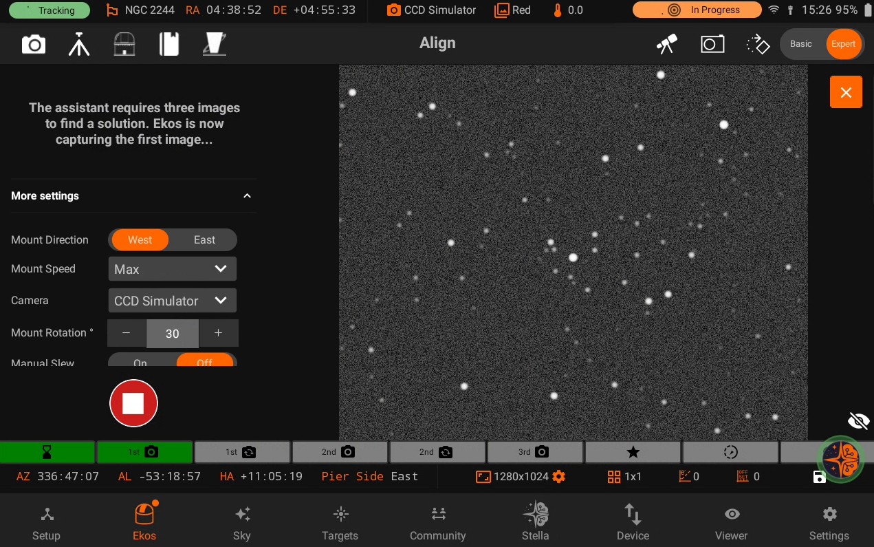
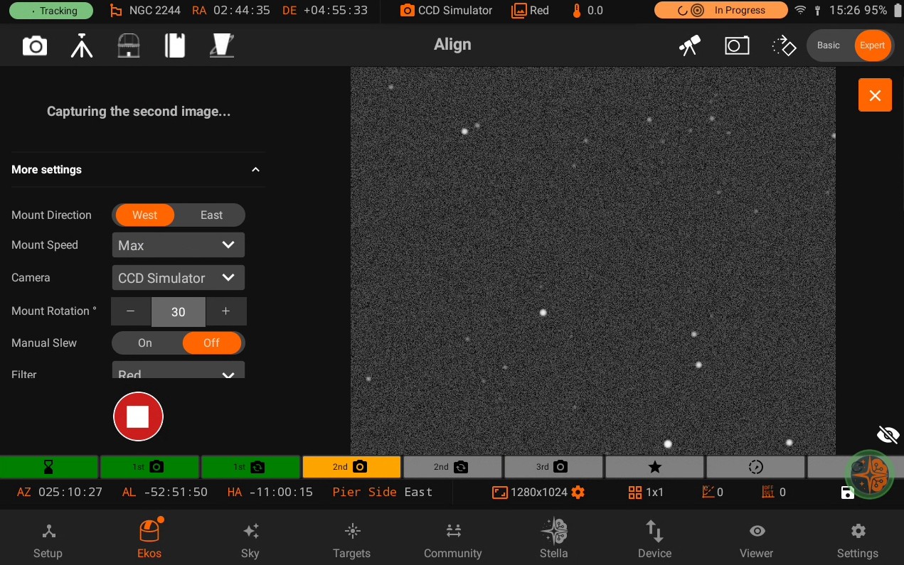
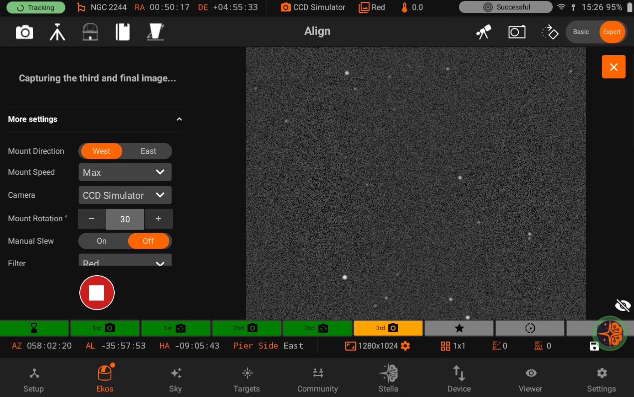
Set the preferred settings and follow the instructions at each step to complete the process.
First Capture
Second Capture
Third Capture
Select Star
Once all 3 images have been captures, you are shown the correction vectors. You can select a star to see the correction vectors relative to the selected star.
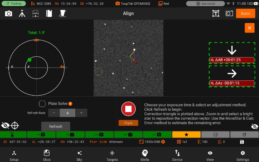
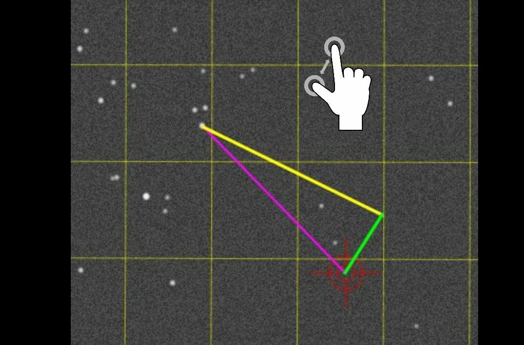
The correction vectors and screen will move to the selected position. At this stage you can use the pinch or spread gesture to use zoom in or out as shown. The zooming and tap features also works while the image is minimized.
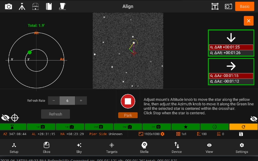
Select Refresh & Algorithm
In the Refresh Stage, the user can adjust the refresh rate by changing the input on the right side, pressing Refresh to start the process.
(Note: at this stage, the refresh only starts once Refresh is clicked)
There are two different algorithms you can choose for PAA:
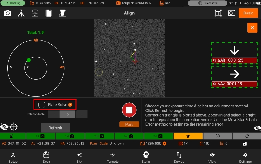
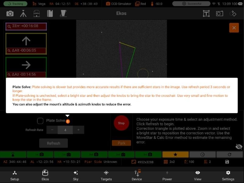
Plate Solving: Uses plate solving to track what the corrected alignment error is during the refresh process . User should try reduce the error in the Updated error line below and minimize the size of arrows. This is the only scheme that can fully correct an error larger than the image field-of-view, but depends on reliable plate solving.
If Plate solve is unchecked, “Move Star & Calc error” Algorithm is used.
Move Star and Calc error: Like Move Star, but Ekos attempts to track the star being moved and estimates the current alignment error when it can.
Refreshing
Refreshing begins and can still be adjusted using the slider. Once done with Polar Alignment, simply press the Stop button.
5.3.5.1.2. Settings
Following settings are from Align module:
5.3.5.1.2.1. Presets
Preset Settings
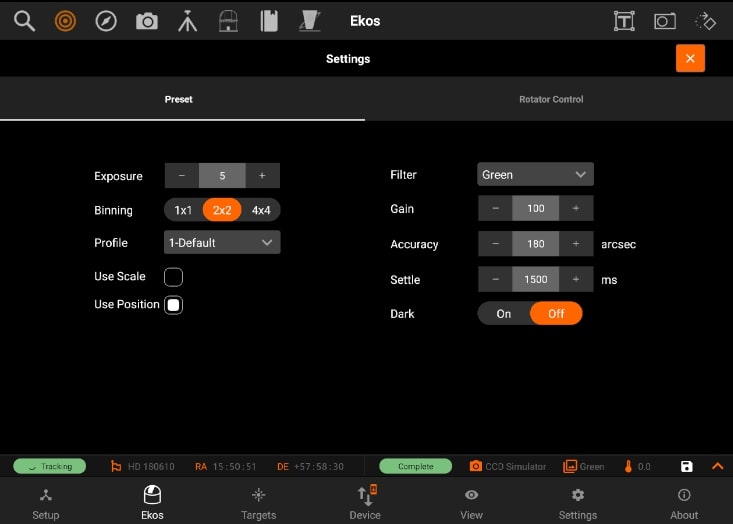
- Preset settings has the following structure:
Profile: Selects the Options profile to use for Plate Sovling.
Use Scale: Use image scale to speed up astrometry solver. This speeds up the solver greatly as it limits the number of images scales it needs to sift through.
Use Position: Limit the astrometry solver to only search for solutions near the mount coordinates. This can significantly speed up the solving process.
Filter
Accuracy: Acceptable difference between reported telescope coordinate and actual solved coordinates
Settle: amount of time to allow mount to settle (in milliseconds)
Dark Frame: Substract Dark frame. Create dark frames or defect maps in the Dark Library tool in the capture module.
5.3.5.1.2.2. Rotator control
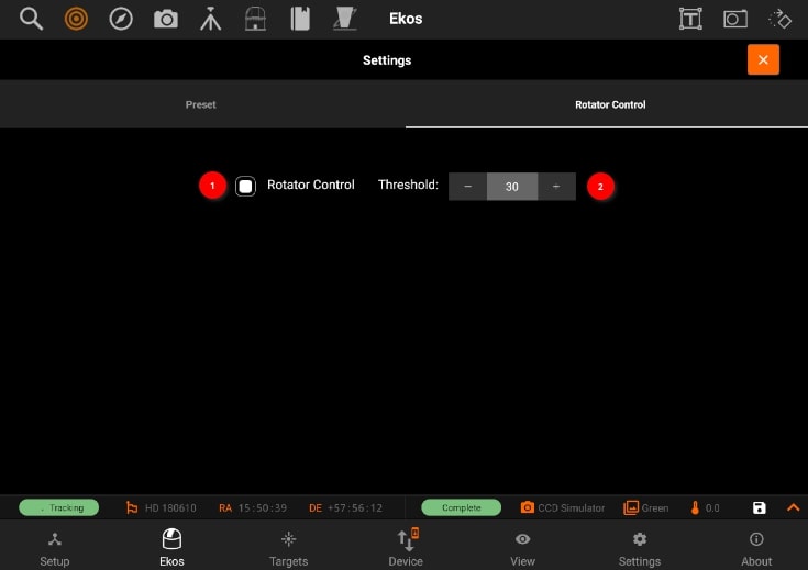
Rotator control
Rotator Control: Use automatic or manual rotation control when using Load & Slew. For automatic control, the mechanized rotator is commanded to rotate to match the desired position angle. For manual control, the user is asked to manually rotate the camera until the desired position angle is reached.
Threshold: Rotator threshold in arc-minutes when using Load & Slew. If the difference between measured position angle and FITS position angle is below this value, the load & slew operation is considered successful.
5.3.5.2. Guide
The Guide module manages guiding the mount to ensure targets are locked at the center during imaging. A dedicated guide camera is required in the secondary optical train. It has the following features:
AI Guiding Assistant
Manage / Select Optical trains.
Start guiding
Preview
Advanced Settings
Image viewer
Guide Plot
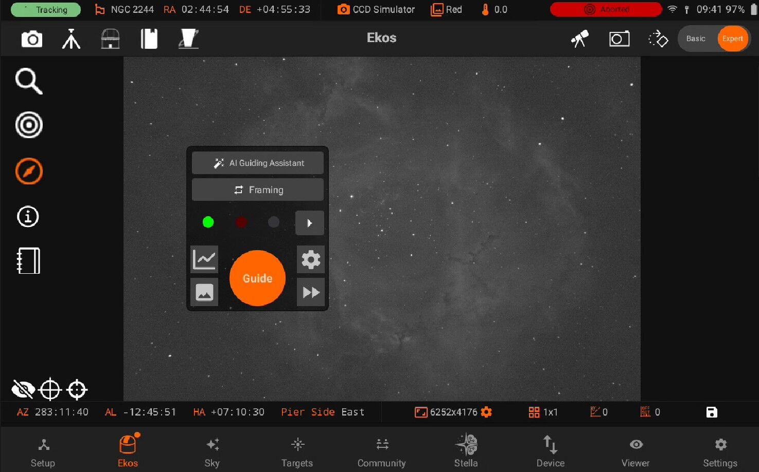
AI Guiding Assistant
The AI Guiding Assistant adds a trained, mount-specific feed-forward predictor to the internal guider. After a one-time training session, the AI learns the repeatable part of your mount’s tracking error — such as periodic error and slow drift — and adds a predicted correction to each guide pulse before the error becomes visible in the guide image. The standard guiding algorithm keeps running underneath at all times and corrects whatever the prediction misses.
Warning
: The AI Guiding Assistant is an experimental feature under active development. Trained models are tied to your specific mount, camera, and guide settings. Always verify your guiding performance after enabling it, and be prepared to switch back to the Standard or GPG algorithms if your results are not better with the AI.
Expectations and Prerequisites
Please read this part carefully before investing time in training a model — it will save you from disappointment later.
Warning
AI guiding augments a well-functioning guiding setup — it does not repair a poorly functioning one. It predicts the repeatable part of your mount’s error and layers that prediction on top of the standard guiding algorithm. It will not fix:
poor polar alignment,
imbalance, cable drag, or differential flexure,
wind gusts, vibrations, or bad seeing,
a mount or guide system that is not already well tuned.
None of these are repeatable errors, so no amount of training can predict them. If standard guiding does not work well on your system, fix that first. The improvement from AI guiding varies considerably from mount to mount, and on some mounts you may see no measurable benefit at all.
Before running the assistant, make sure that:
You are using the internal guider, with a working guide camera and a completed, successful calibration.
Ordinary guiding with the Standard algorithm already works reliably on your setup.
Your mount is well polar-aligned, balanced, and free of cable snags.
You know your mount’s drive type: worm gear (most equatorial mounts), harmonic/strain-wave drive, or direct drive.
Your guide exposure is the one you intend to keep using: the model is trained and locked to the guide exposure, binning, and guide settings used during data collection.
You have 20–45 minutes of clear, reasonably steady sky to spend on data collection, depending on the mount type.
Data Collection with the AI Guiding Assistant
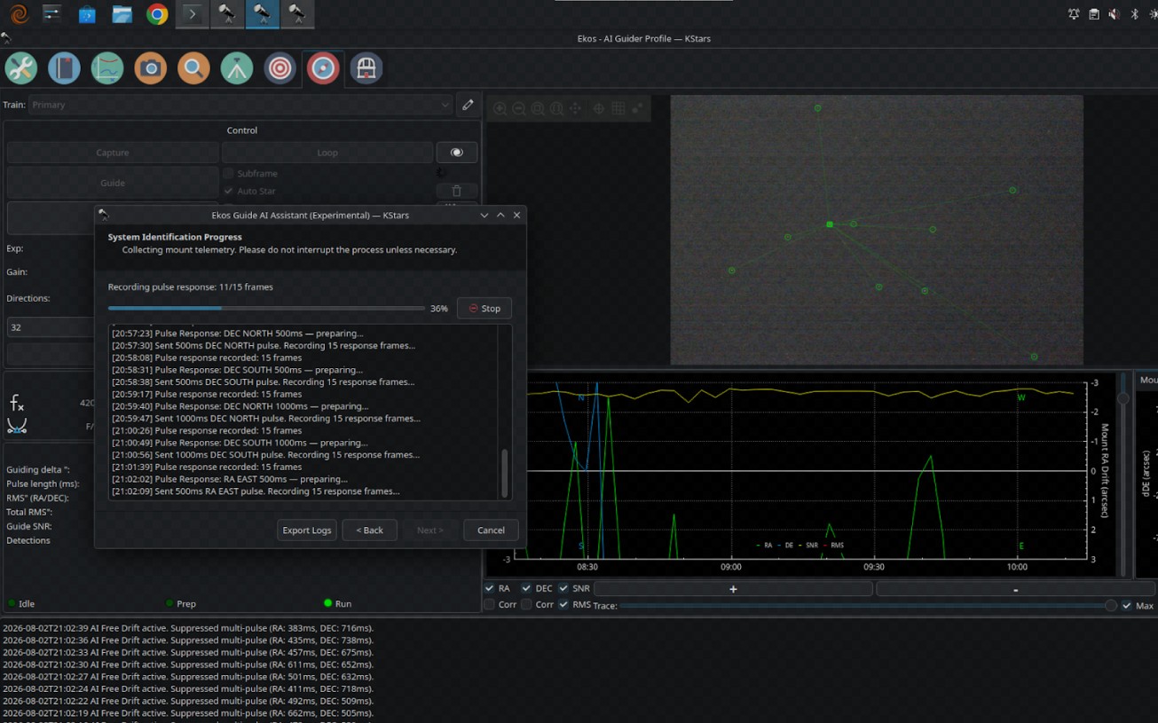
Training a model starts with a system identification session: the assistant points the mount at a few positions in the sky and records how the guide star drifts, both with guiding running and with guiding deliberately paused (“free drift”), so that the mount’s raw error signature can be measured. Click AI Guiding (Experimental) → AI Guiding Assistant… on the Guide page to start the wizard.
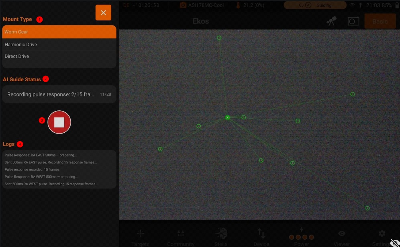
Verify the detected mount type: - Worm Gear - Harmonic Drive - Direct Drive. Also recommends a guide exposure per drive type — 2.0 s for worm gears, 0.5–1.0 s for harmonic drives (depending on guide star signal), and 1.0–3.0 s for direct drives. Set your exposure before proceeding: the trained model is locked to it.
The protocol depends on the mount type:
Worm Gear (~45 minutes): three pointings at high, lower, and high altitude, each combining standard guiding with several minutes of free drift. The long free-drift phases capture roughly three full worm cycles, which is what allows the periodic error to be measured.
Harmonic Drive (~35 minutes): free drift and standard guiding at two pointings, plus a series of short pulse-response tests (50, 100, and 200 ms pulses in all four directions) that measure how the drive reacts to corrections.
Direct Drive (~20 minutes): short guiding and free-drift phases at three different altitudes.
Press the Play button to start the guider, then monitor the AI Guider log for status updates.
Guide Quick Settings
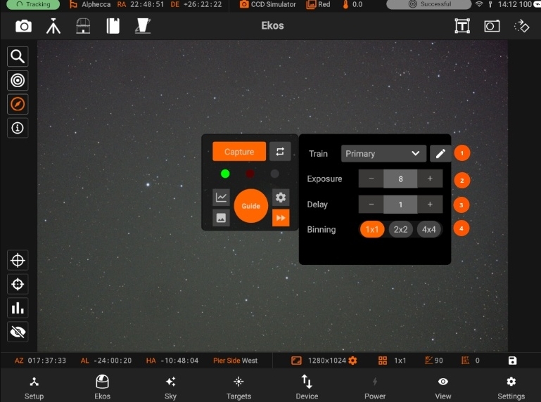
Train: You can Select / Edit a train specifically for Align module. Each module has it’s own train. Visit Optical trains topic for more.
Exposure: Exposure time in seconds
Delay: Delay in seconds between image captures.
Binning: Guide camera binning. It is recommended to set to 2x2 or higher.
Guiding
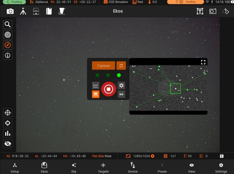
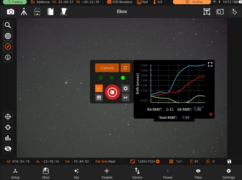
You can start guiding by tapping on the Start button. The guide module will start by calibrating, and then will start the guiding process. When guiding is in progress, you will be able to see the Guide plot being populated with lines for the RA drift, DE drift and the Total RMS. You can also check the values for RA RMS, DE RMS and Total RMS under the plot.
5.3.5.2.1. Settings
Following are the settings from Guide module:
Preset settings Advanced settings Calibration settings
5.3.5.2.1.1. Preset
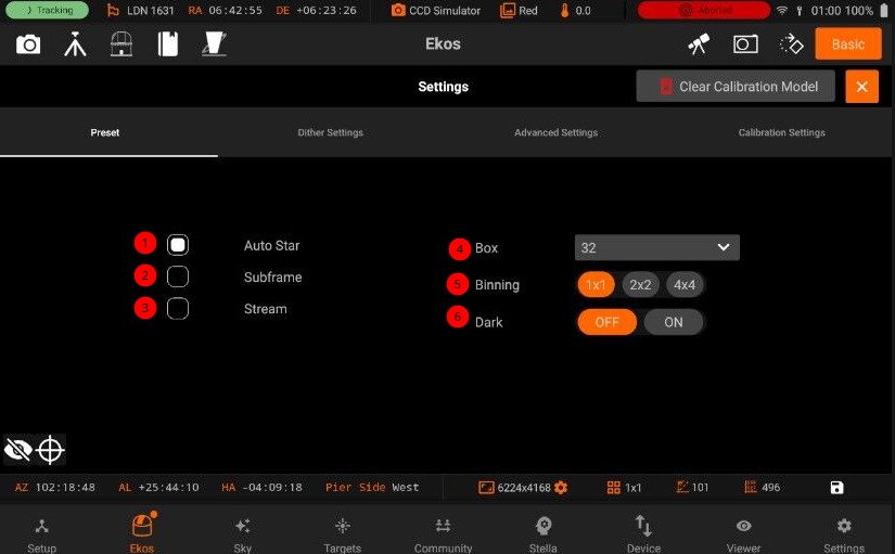
1. Auto star: Automatically select the calibration star. SEP Multi Star does always use ‘auto star’ detection.
2. Subframe: Subframe the image around the guide star. Or for PHD2, receive the Guide Star Image instead of the full image frame. For the Internal Guider, before checking this option, you must first capture an image and select a guide star. Uncheck it to take a full frame again.
3. Stream: Enable streaming guide mode. When checked and the camera supports video streaming, the guide module captures frames via a continuous video stream instead of individual exposures. This significantly reduces per-frame overhead and enables higher guiding frequencies (e.g. 2-5 Hz) required by harmonic drives. Not compatible with dark-frame subtraction.
4. Box: Guide star tracking box size. Box size must be set in accordance to the selected star size.
5. Binning: Guide camera binning. It is recommended to set binning to 2x2 or higher.
6. Dark: Subtract dark frame. If no dark frame is available, a new dark frame shall be captured and saved for future use.
5.3.5.2.1.2. Dither
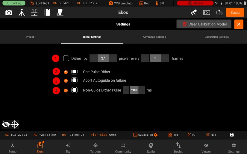
1. Dither: Allows manual dithering. 3. Pulse: If checked, dithering amount is randomly generated, pulses are sent, but the resultant pixel dithering amount is not enforced so only the one dither pulse is sent. This is quicker, and recommended as dither amount is random anyway. It is necessary when 2-D dither is required but guiding is only done in one axis 4. Abort Autoguide:: Abort Autoguide on failure 5. Perform Dithering: Perform dithering, When not guiding
5.3.5.2.1.3. Advanced
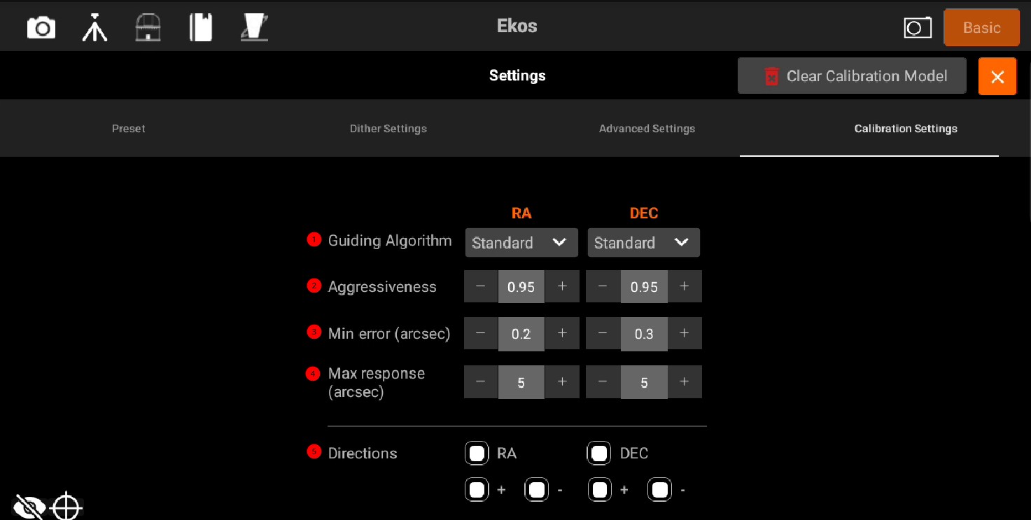
1. Algorithm: Select the guide pulse algorithms for RA and DEC. * Standard: The traditional proportional guide algorithm. It computes a pulse to correct the computed guide drift. The aggressiveness parameter decides what proportion of the error is corrected. Errors smaller than MinError won’t be corrected. Max response limits the largest correction. The hysteresis parameter is not used. * Hysteresis: Hysteresis is like the standard algorithm but weights in the previous correction according to the hysteresis parameter. Integral gain does not apply. •Linear: This is similar to the PHD2 Lowpass2 algorithm. It computes the error pulses based on a short history of recent errors. This may be applicable to very stable mounts. Hysteresis and Integral gain do not apply. * GPG: (RA Only) The GPG algorithm tries to predict periodic error and linear drifts. It uses the aggressiveness, min and max parameters here, and more parameters on the separate GPG tab. Hysteresis and Integral gain do not apply. 2. Aggressiveness: How aggressively the guider attempts to correct the guide deviations. 1.0 would attempt to fully correct the error. It’s best to use an aggressiveness less than 1.0 to avoid oscillations. 3. Min Error (arcsec): Minimum guide deviation in arc-seconds for which a guide pulse would be sent to the mount. If the guide error is less than this value, then no pulse is sent to the mount. 4. Max Response (arcsec): Maximum guide pulse that is generated by the guider and sent to the mount in arc-second units. That is, the guider will not attempt to move the mount more than this many arc=seconds at any given time.
Directions: Shows the values of RA and DEC. 5. RA: Guide Right Ascention Axis
+: East Direction Guiding
-: West Direction Guiding
6. DEC: Guide Declination Axis
+: North Direction Guiding
-: South Direction Guiding
5.3.5.2.1.4. Calibration
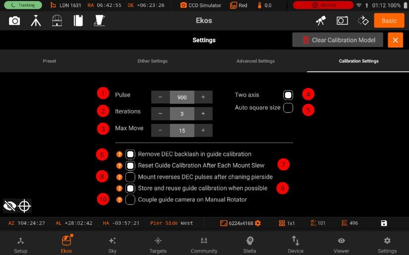
1. Pulse: Initial pulse size for calibration.
2. Iterations: Maximum number of iterations calibration should use per phase. It may use fewer (If max move is reached).
3. Max move: Maximum number of pixels the calibration should move. Once it exceeds this amount, it will finish the calibration phase. It may move less if max iterations is reached.
4. Two axis: Check if you want the calibration process calibration in both RA & DEC. If unchecked, the calibration is only performed in RA.
5. Auto square size: Automatically select the square size based on the selected star width.
Checkbox options * 6. calibrate_backlast: Remove DEC backlash in guide calibration * 7. reset_calibration: Reset Guide Calibration After Each Mount Slew * 8. pierside: Mount reverses DEC pulses after chaning pierside * 9. reuse_calibration: Store and reuse guide calibration when possible * 10. Manual rotator: Couple guide camera on Manual Rotator
5.3.5.2.1.5. AI Guider
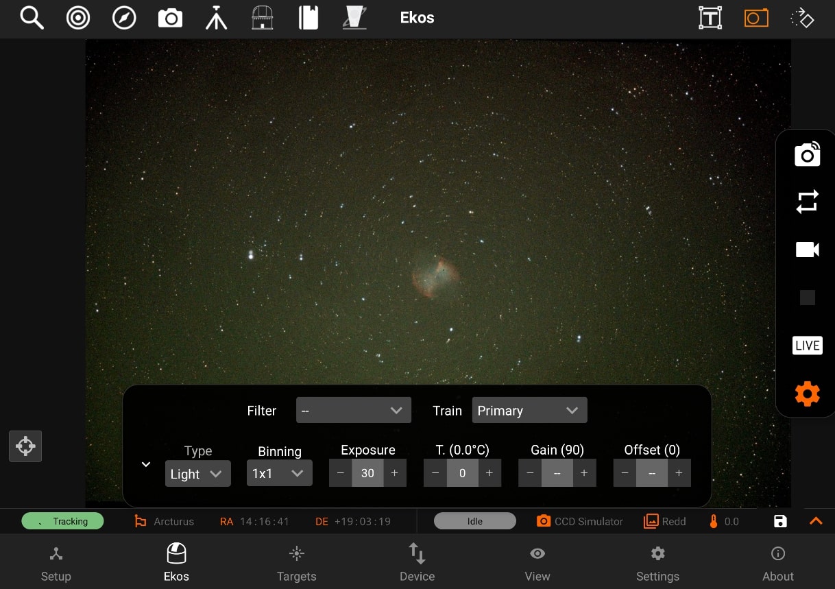
Weights File: path to the trained model weights (JSON).
AI Prediction Gain (default 0.5): how strongly the AI prediction is blended into the guide pulses. 0.0 ignores the AI entirely; 1.0 applies its full prediction. Start at the default and increase gradually if guiding improves.
Dark Guiding Interval (default 1.0 s): seconds between predicted pulses when no guide-star measurement is available.
Scale Down Proportional: Gain During AI Correction (default off): reduces the standard proportional response by up to half when the AI is highly confident, to avoid the two controllers over-correcting the same error.
Enable Predictive Dark Guiding (default off): keeps emitting predicted corrections during gaps in guide star measurements — dither settling, autofocus runs, or camera downloads — by extrapolating the periodic error forward in time.
5.3.5.3. Capture
The Capture module is the primary interface for managing imaging tasks on StellarMate. It allows you to preview images, configure settings, create capture sequences, and configure imaging settings.
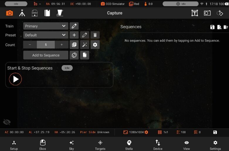
All captures are performed using an Optical Train. An optical train is a collection of devices including camera, telescope, mount, filter wheel, and other devices that work together to capture images.
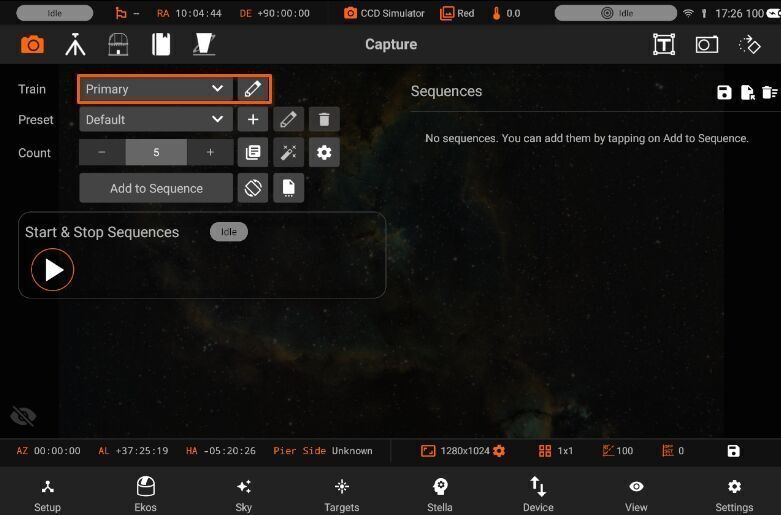
The terms Sequence and Job are used interchangeably in this document.
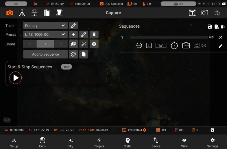
Sequences are a collection of capture jobs. Each job is defined by a preset that specifies the imaging parameters. These parameters include exposure time, binning, filter, and other settings.
To create a new sequence, select a preset and specify the desired number of images to capture (count). Then, tap “Add to Sequence” to add the job to the Sequence Queue.
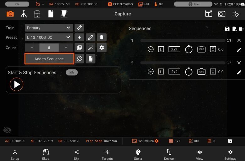
This structure allows you to efficiently capture multiple images with consistent settings, making it easier to manage your astro-photography sessions. The left side of the Capture module is used to configure settings, optical trains, and presets, while the right side displays a list of sequence jobs.
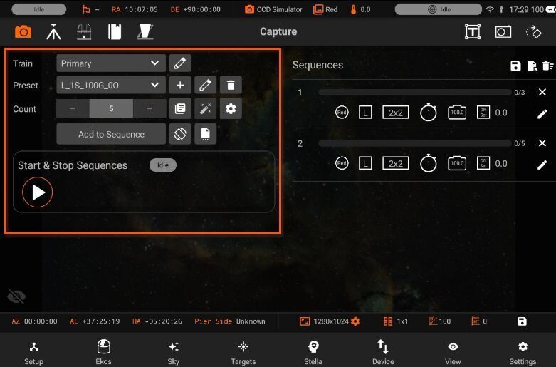
5.3.5.3.1. Presets
A preset is a collection of settings for a single capture job. These settings are applied to each capture job, while the capture settings are applied globally to all jobs.
When creating a new preset, the preset label is automatically generated based on the selected settings (e.g., exposure time, binning, filter). This helps you easily identify presets in the future.
To add a new Capture Preset, tap the + icon.
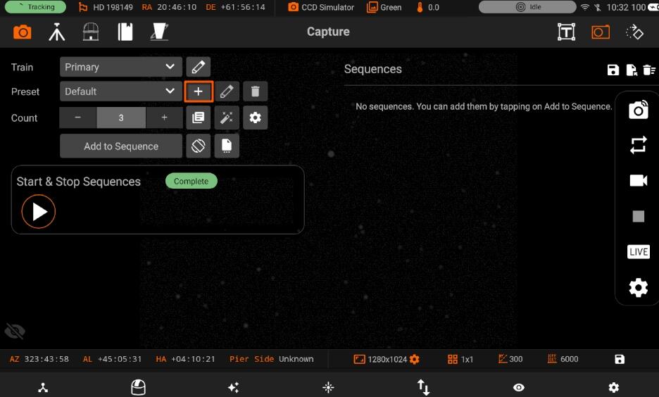
All settings marked with “–” mean leave as-is. For example, if the current gain is 100, and the job is executed, the gain would be left as-is.
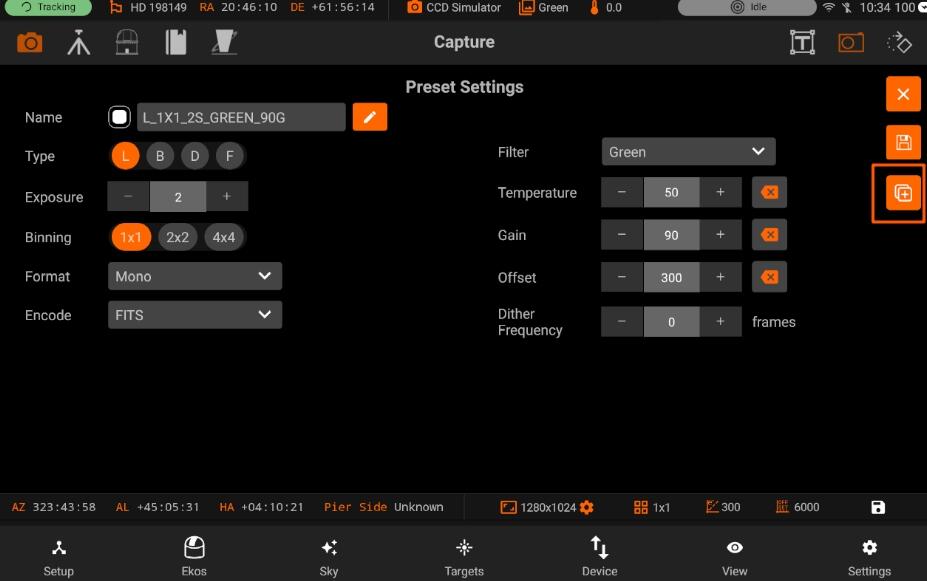
Once you press the Saved button (on the right side) Preset will get saved.
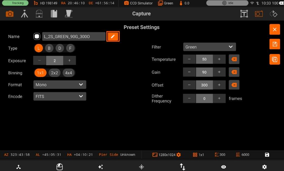
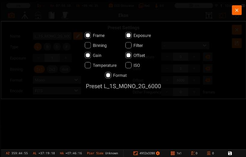
To customize the preset label generation, tap the “Edit” icon next to the preset name. You can modify the label format to suit your preferences
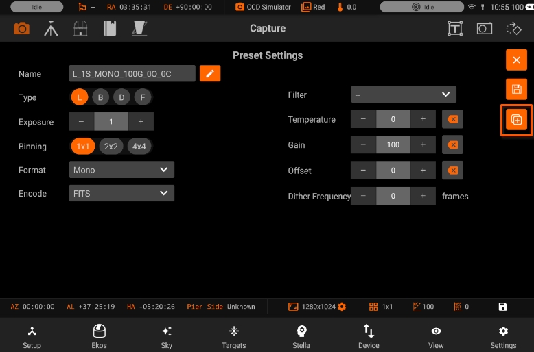
When you edit a preset, you can also duplicate the Preset. Duplicating a preset can be handy when you need to only alter one or two fields while keeping the rest the same. To duplicate a preset, tap on the duplication icon.
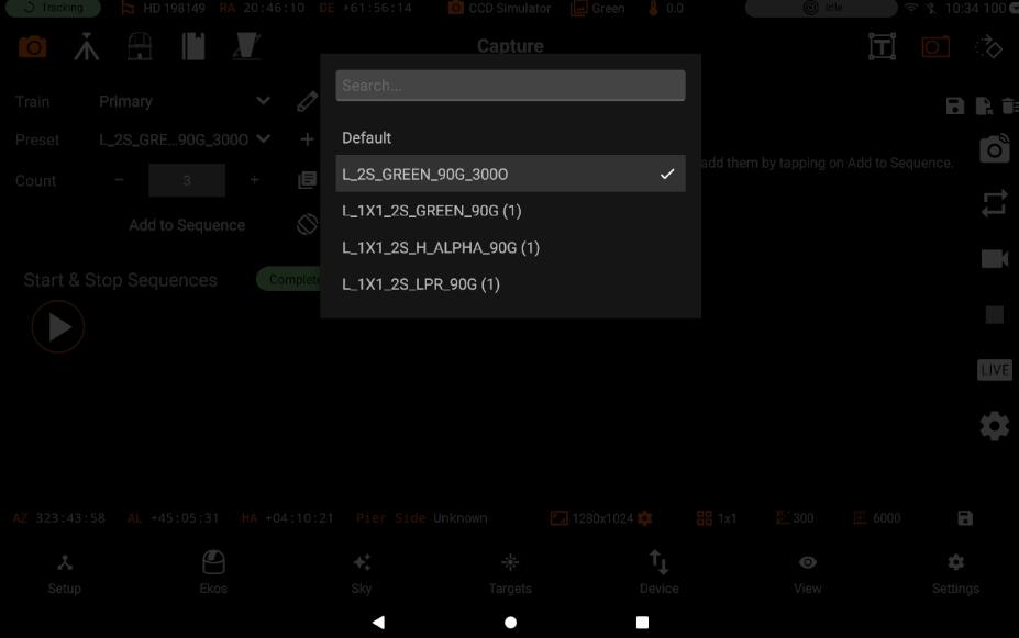
You can also create the same preset with the multiple filter names. Hence with multiple filter names you can have presets as shown in the screenshot below:
Preset Editor contains the following fields:
Preset name: Name of the preset.
Frame Type: Specify the type of desired camera frame. Options are Light, Dark, Bias, and Flat frames.
Exposure: Specify exposure duration in seconds.
Binning: Specify horizontal (X) and vertical (Y) binning.
Format: Specify capture save format (FITS, XISF, or Native when available)
Encoding: For DSLR cameras, you can an additional option to save in Native format (e.g. RAW or JPEG).
Filter: Specify desired filter.
Temperature: Set the desired temperature, if your camera is equipped with a cooler. Check the option to force temperature setting before any capture. Capture process is only started after measured temperature is within requested temperature tolerance
Gain: Specify the value of gain. Leaving it to – would not change the current gain set in the camera
ISO: For DSLR cameras, specify the ISO value.
Offset: Specify the value added to avoid the reads to clip at value “zero”. Leaving it to – would not change the current offset set in the camera.
Dither frequency:
5.3.5.3.2. Sequences
Manage, save, and load sequences in the sequence queue.
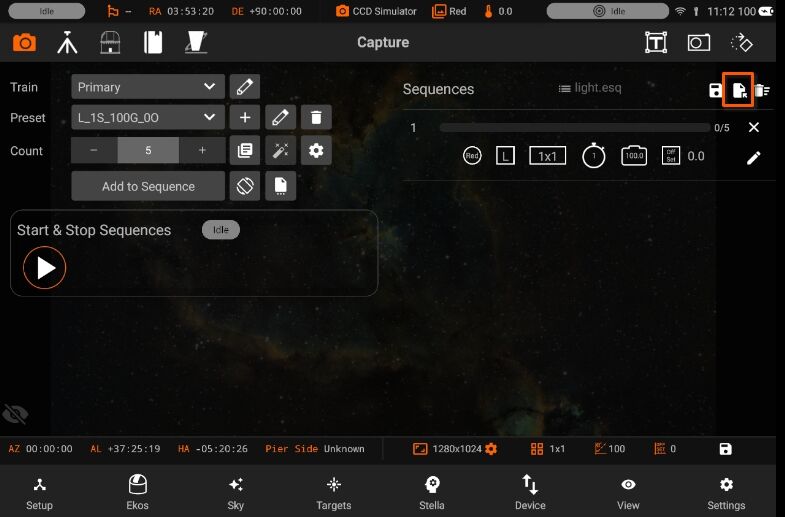
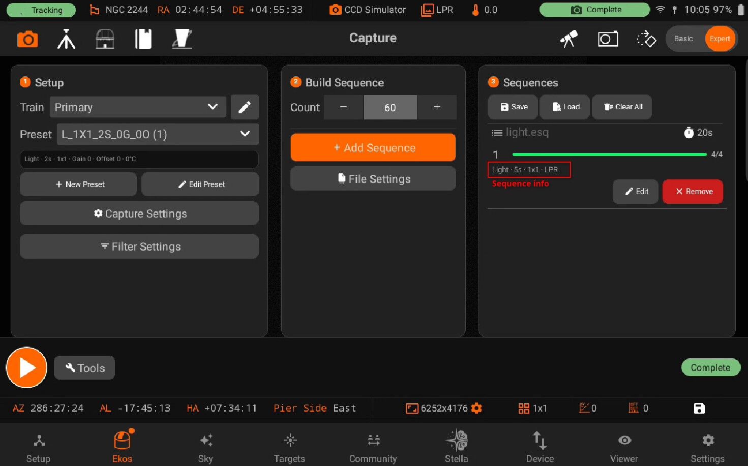
The queue displays a list of sequences where each sequence status, count, and preset is displayed using icons for common settings such as Filter, Gain, ISO, and Offset.
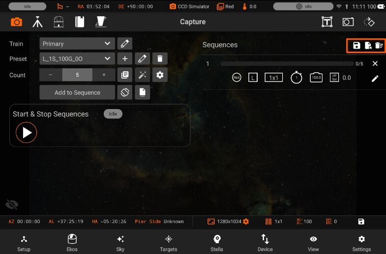
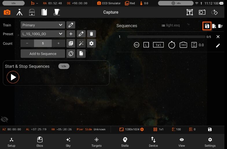
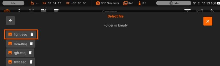
Once a sequence is added, you can save the sequence list by tapping on the Save Icon on the top-right. Tap the trash icon to clear all jobs.
Sequences are stored under the Documents folder followed by your camera name. The sequence file can be re-used in future sessions when desired, especially when using the scheduler.
Sequences have the following structure, displayed through icons for simplicity:
Top row
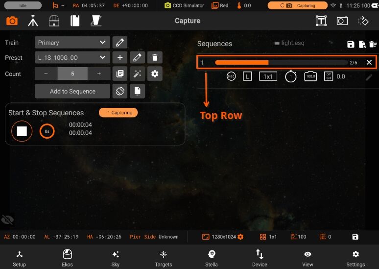
Job Number
Job Progress Bar
Count Progress
Delete Job
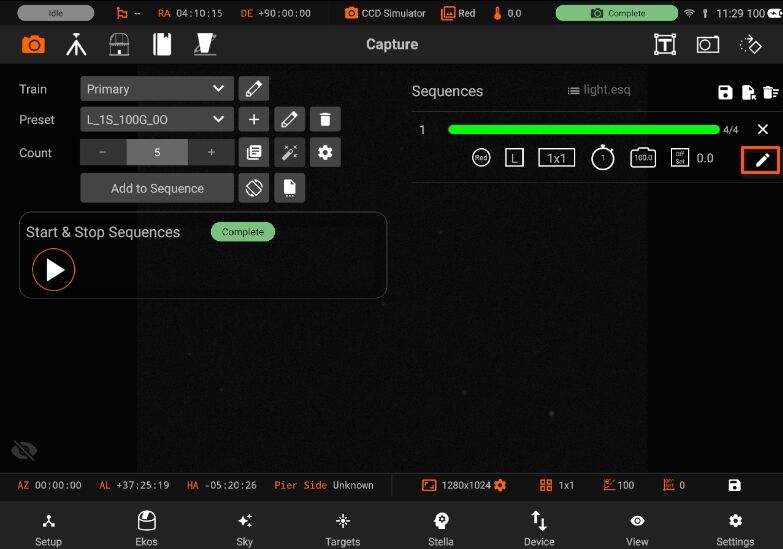
Bottom row
Filter
Frame Type
Binning
Exposure
Gain/ISO
Offset
Edit Sequence
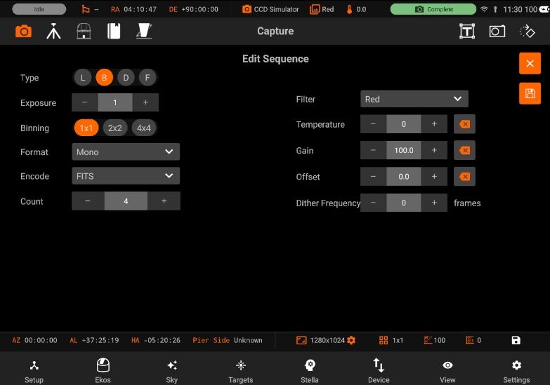
After adding the sequences, tap on the Play button under the Progress header to start the capture process. A soft ding sound is played for each captured image (if enabled in settings).
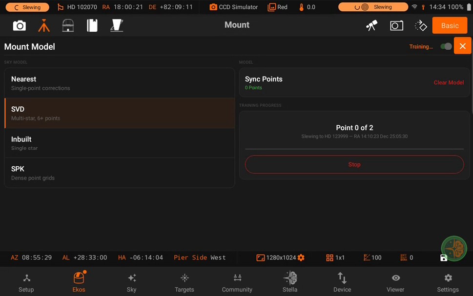
5.3.5.3.3. Dark Library
Dark Library
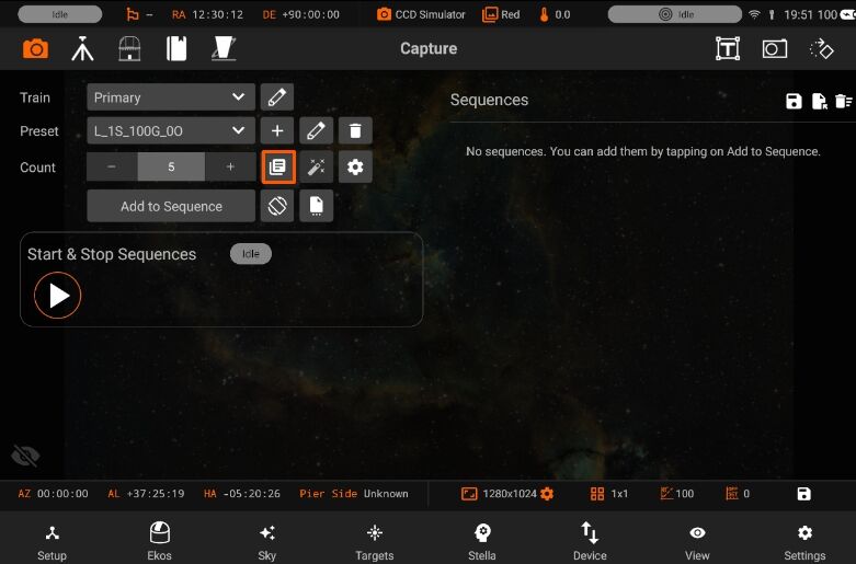
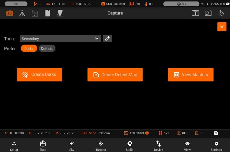
The Dark Library is a collection of dark frames captured from your cameras under different settings. There are basically five primary types of frames:
Light Frame: This is the regular image captured by your sensor. It is called light because it captures the incoming light received at the sensor.
Dark Frame: A frame captured with the same settings as the light frame (same temperature, exposure time, and binning) but with the shutter closed so that no photons reach the sensor. This is used to record the electronic noise generated by the sensor without any incident photons. It is used to remove noise from the Light Frame by means of subtraction since the Light Frame includes signal from both the incoming photons and electronic noise generated by the sensor.
Bias: A very short exposure with the shutter closed.
Flat: A frame captured with the same settings as the light frame (same temperature, exposure time, and binning) but subjected to an illuminated flat field source (such as an LED panel). This is used to correct for optical aberrations in the imaging train including dust motes.
Dark Flats: Special type of dark frames captured at the same exposure of flat frames. This is used to calibrate the flat frames.
Dark Library is used to capture dark images.
Generating a dark library for your equipment profile is highly recommended. When capturing frames in focus, guide, and align modules, the system searches the dark library for suitable dark frames. If a suitable match is found, the light frame is calibrated and this can greatly enhance the performance and accuracy of all Ekos modules.
Note: “Dark Library is not used to calibrate your sequence images, it is only used to calibrate the Align, Focus, and Guide module frames.”
Dark frame calibration can be applied using two methods:
Dark Subtraction: The dark frame is simply subtracted from the light frame. This is the recommended method when using a cooled camera.
Defect Maps: For uncool-ed cameras (e.g. Guide), dark frames may not be suitable for removing the hot and pixels present in the image. An alternative method generates a map of bad pixels that should be treated in the light frame. You can adjust the Hot and Cold pixels sliders to include or exclude pixels. It’s recommended not to include more than 5,000 pixels as it can become computationally expensive to correct this many pixels in guide images. Ekos corrects each defective pixel by using calculating the median value from surrounding pixels.
Preset: Select which capture preset to use. The camera name, gain, and offset are used from the preset while the exposure and temperature settings (if supported) are configured in the Create Dark Library window.
- Prefer: Select which dark calibration method to utilize for the selected preset. Both methods are used to remove noise from the light frame:
Dark: Remove noise by means of dark frame subtraction.
Defect Maps: Remove noise by means of defect map substitution.
1. Create Darks:
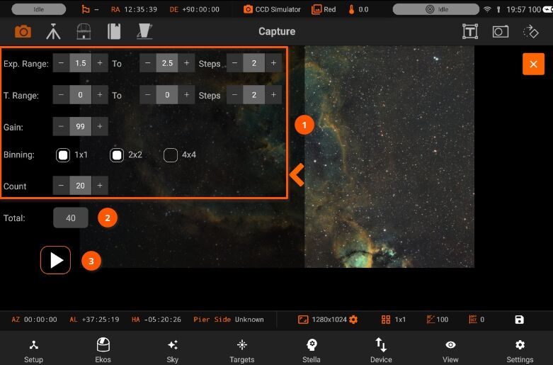
Create a master dark frame by capturing and averaging a number of individual dark frames.
Select the range of exposures, binning, temperatures and count (if applicable) required.
Each time you change a selection, the Total Frames count is updated to reflect the required frames.
When ready, tap the Play button to start the process.
2. Create Defect Map:
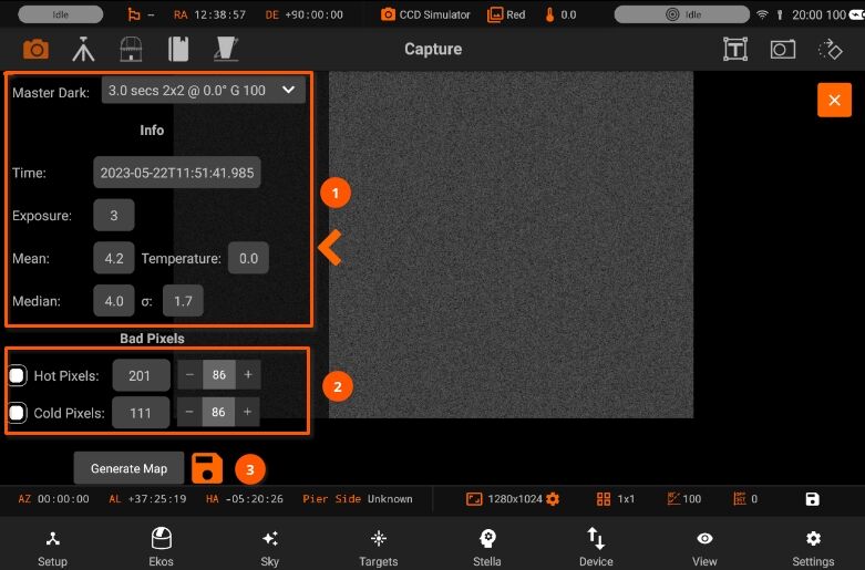
- After creating a master dark, you can create a defect map for your camera. Usually, defect maps are used when dark frame subtraction does not improve the quality of the calibration result. This is especially evident when using uncool-ed guide cameras that can exhibit hot pixels that are hard to treat with classical dark frame subtraction methods.
Selecting the master dark frame, loads the information of the image
Then adjust Hot and Cold pixel sliders to include or exclude pixels.
Click Generate Map to inspect the results and once satisfied tap the save button to store the defect map for future use.
3. View Masters:
Inspect master frames of a specific camera.
5.3.5.3.4. Rotator Control
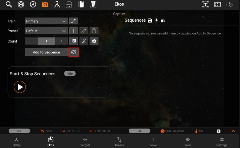
Rotator control settings are available if Rotator is selected in the active train.
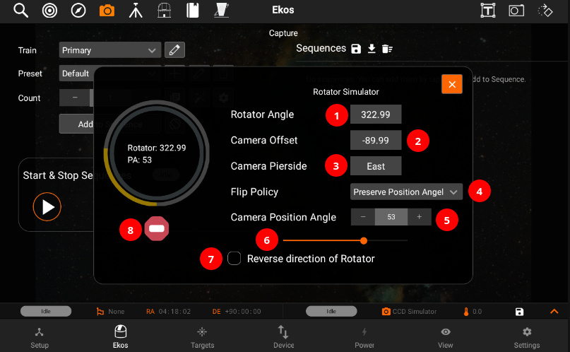
The raw rotator full circle angle of the rotator device, which is calculated as the difference of the rotator origin (zero angle) respective to North on pierside WEST or respective to South on pierside EAST.
The angle of the camera upright direction (see FOV) respective to the rotator origin direction. The camera offset is determined automatically by a Capture & Solve or a Load & Slew in the Align module. The camera offset is measured in position angle scope (-179.99° to 180.00°).
The current pierside of the mount. A red frame indicates an unknown pierside. This is normal if the mount is parked.
Flip Policy determines how the rotator reacts after a flip or if the result of a solved reference image reports a different pierside respective to the actual mount pierside.
Setting the camera position angle shall move the rotator. The gauge reflects the state of the rotator. Depending on the accuracy of the rotator there can be some deviation in the ending position angle. If Save Camera Position Angle to Sequence Job is toggled, any subsequent jobs added to the sequence queue would always rotate to this position angle before capture begins. The position angle is measured East of North in degrees.
Change Camera position angle.
Reverse the direction of rotator.
Abort Rotator movement.
5.3.5.3.5. Files
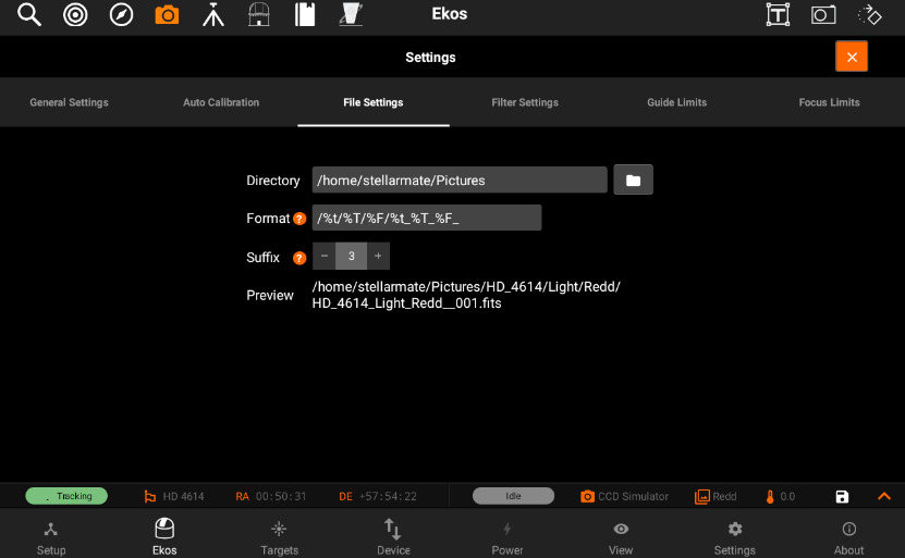
- Settings for specifying where captured images are saved to, and how to generate unique file names.
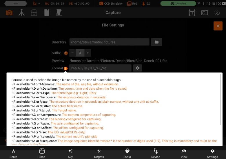
Directory: Local directory to save the sequence images to. Format: Format is used to define the image file names by the use of placeholder tags.
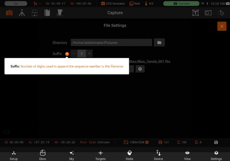
Suffix: Number of digits used to append the sequence number to the filename
Preview: Path of your filename
You can now also unmount your USB device by pressing “Unmount” button next to your external storage device.
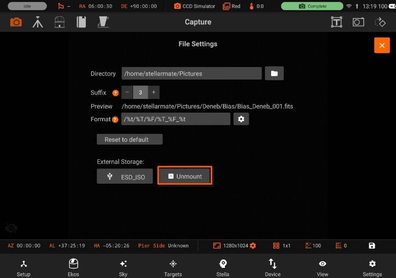
You can also set the directory path of your USB device (if attached). If USB device is connected, then External Storage devices are visible. By selecting on of them, will set the Directory path of it.
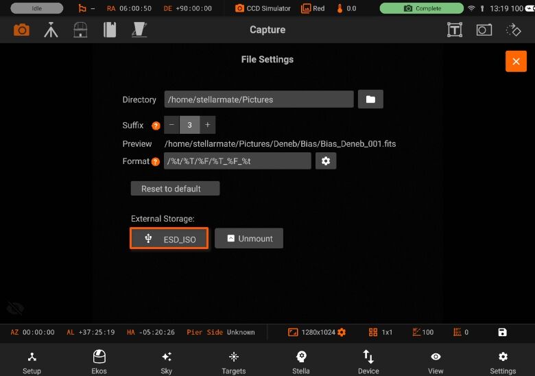
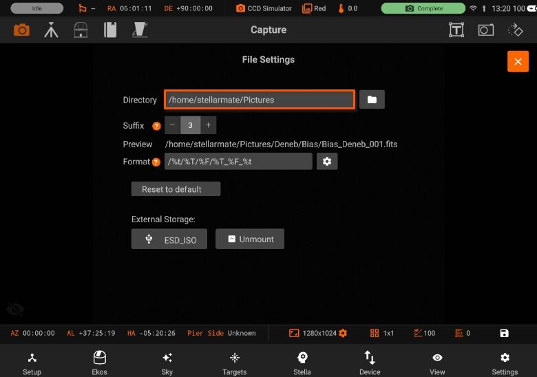
5.3.5.3.6. Settings
Following are the settings from Capture module:
General Settings
Auto Calibration
Filter Settings
Guide Limits
Focus Limits
5.3.5.3.6.1. General
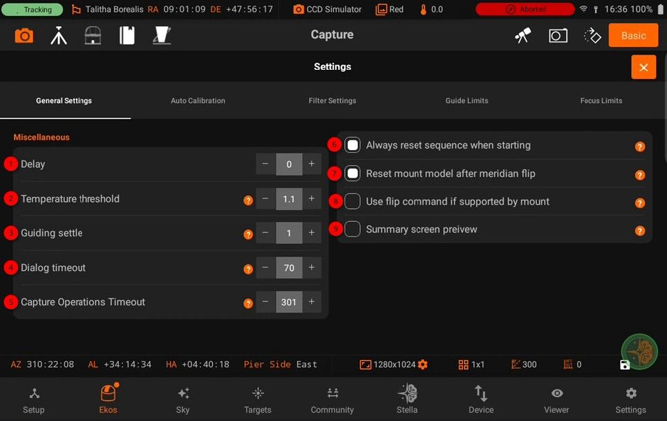
Delay in seconds between consecutive images.
Maximum acceptable difference between requested and measured temperature set point. When the temperature threshold is below this value, the temperature set point request is deemed successful.
Wait this many seconds after guiding is resumed to stabilize the guiding performance before capture.
Cover or uncover telescope dialog timeout in seconds
Maximum number of seconds to wait before aborting the capture if operations like filter wheel changes or meridian flips take too long. Also bounds the time the Scheduler spends establishing guiding (Calibration and lock) before starting capture. )
When starting to process a sequence list, reset all capture counts to zero. Scheduler overrides this option when Remember job progress is enabled.
Reset mount model after meridian flip
Use flip command if it is supported by the mount.
Display received FITS in the Summary screen preview window.
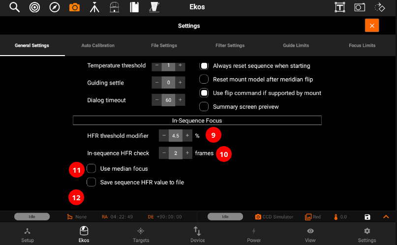
Set HFR Threshold percentage gain. When an autofocus operation is completed, the autofocus HFR value is increased by this threshold percentage value and stored within the capture module. If In- Sequence-Focus is engaged, the autofocus module only performs auto-focusing procedure if current HFR value exceeds the capture module HFR threshold. Increase value to permit more relaxed changes in HFR values without requiring a full autofocus run.
Run In-Sequence HFR check after this many frames.
Calculate median focus value after each autofocus operation is complete. If the autofocus results become progressively worse with time, the median value shall reflect this trend and prevent unnecessary autofocus operations when the seeing conditions deteriorate.
In-sequence HFR threshold value controls when the autofocus process is started. If the measured HFR value exceeds the HFR threshold, autofocus process is initiated. If the HFR threshold value is zero initially (default), then the autofocus process best HFR value is used to set the new HFR threshold, after applying the HFR threshold modifier percentage. This new HFR threshold is then used for subsequent In-Sequence focus checks. If this option is enabled, the HFR threshold value is constant and gets saved to the sequence file.
5.3.5.3.6.2. Auto Calibration
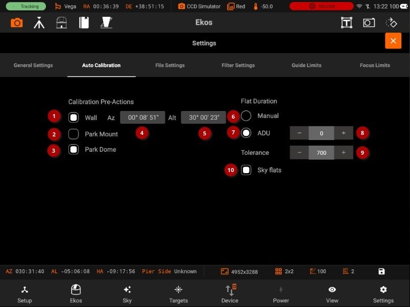
Note: You can only edit calibration settings for capture jobs that have the frame type as Bias (B), Dark (D), or Flat (F).
For Flat Field frames, you can set calibration options in order to automate the process. The calibration options are designed to facilitate automatic unattended flat field frame capture. It can also be used for dark and bias frames if desired. If your camera is equipped with a mechanical shutter, then it is not necessary to set calibration settings unless you want to close the dust cover to ensure no light at all passes through the optical tube. For flat fields, you must specify the flat field light source, and then specify the duration of the flat field frame. The duration can be either manual, or based on ADU calculations.
Wall: Slew mount to the specified Azimuth/Altitude coordinates before taking flat field images
AZ: Slew mount to the specified Azimuth/Altitude coordinates before taking flat field images
ALT: Select which actions to perform before a Bias/Dark/Flat frame is captured
Park mount: Select which actions to perform before a Bias/Dark/Flat frame is captured.
Park dome: Select which actions to perform before a Bias/Dark/Flat frame is captured
Flat Field Duration:
Manual: Use the frame exposure value
ADU: Calculate optimal exposure time given the required ADU. If a controllable device is selected, calculate optimal brightness.
Tolerance: Accept ADU values that fall within this range around the desired ADU C target. For example, if the ADU value was set to 10000 and the tolerance was set to 100, then frames with ADU values f 9900 and 10100 shall be accepted.
Sky flats: When shooting flats on sky that can change intensity. Will use simpler exposure calculation.
Before the calibration capture process is started, you can request Ekos to park the mount and/or dome. Depending on your flat source selection above, Ekos will use the appropriate flat light source before starting flat frames capture. If ADU is specified, Ekos begins by capturing a couple of preview images to establish the curve required to achieve the desired ADU count. Once an appropriate value is calculated, another capture is taken and ADU is recounted until a satisfactory value is achieved.
5.3.5.3.6.3. Filters
You can edit filters by tapping on the Filter button. The filter settings page will open and allow you to edit filter settings for each filter of the filter wheel selected in the drop-down menu.
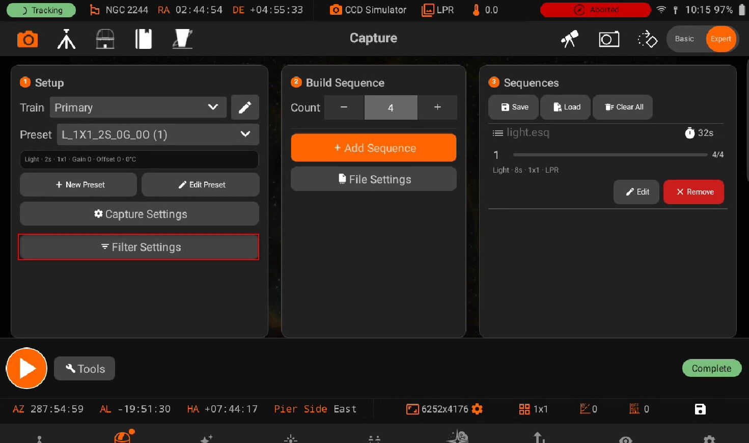
Configure settings for each filter individually:
Name: Filter Name
Exposure: Set exposure time used when performing focus under this filter. By default, it is set to 1 seconds.
Offset: Set relative offsets. Ekos will command a focus offset change if there is a difference between the current and target filter offsets. For example, given the values in the example image to the right, if the current filter is set to Red and next filter is Green, then Ekos shall command the focuser to Focus In by +300 ticks. Relative positive focus offsets denote Focus Out while negative values denote Focus In.
Auto Focus: Check this option to initial AutoFocus process whenever the filter is changed to this filter.
Lock Filter: Set which filter should be set and locked when performing autofocus for this filter.
Let’s take an example. Suppose the capture sequence is running and the current filter is Green, so the relative already offset is set to +300. The next image in the sequence uses Hydrogen Alpha (H_Alpha) so before Ekos captures the next frame, the following actions take place:
Since Lumonisity is specified as the locked filter and auto-focus is checked, the filter is changed to Lumonosity
A focus offset is -300 is applied since the prior filter Green was moved +300 previously.
Auto Focus process is initiated.
Once Auto Focus is complete, the filter is changed to H_Alpha.
A focus offset of -1200 is applied.
Capture sequence is resumed.
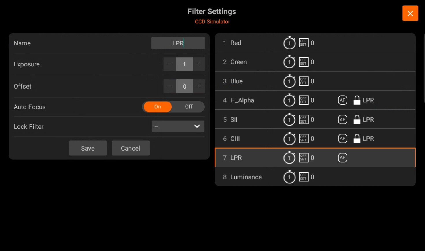
To edit a filter, tap on it on the panel on the right-side of the page. All of its details will be filled in the panel on the left-side to be edited.
After you edit the filter, tap on the Save button to save the filter settings. The panel on the right-side will shown the new settings for the filter you just edited.
5.3.5.3.6.4. Focus
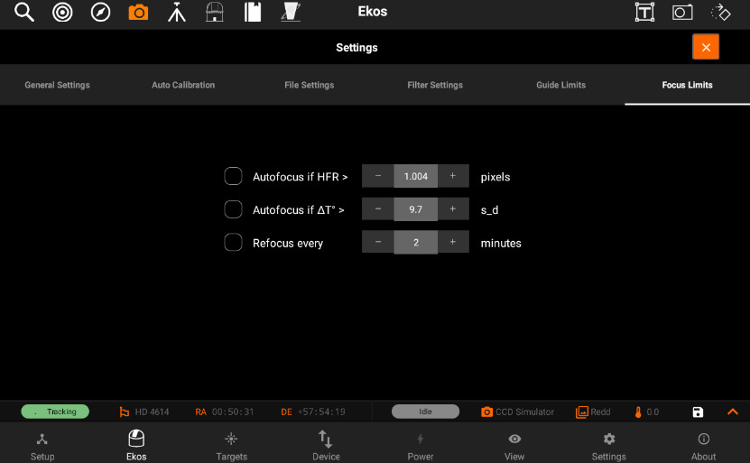
Focus limits settings are applicable to all the images in the sequence queue. When a limit is exceeded, Ekos shall command the appropriate action to remedy the situation as explained below:
Refocus every: Check to force an Autofocus every N minutes. Timer is reset at each Autofocus. Refocus value in minutes
Autofocus: Check to force an Autofocus when the change in temperature since last focus exceeded this value. Reference temperature is reset at each Autofocus.
Refocus meridian flip: Check to force an Autofocus after a Meridian Flip.
Refocus on HFR: Check to perform an HFR Check between Subframes. The Check may result in an Autofocus.
- Algorithm: The HFR Check algorithm:
Last Autofocus: This is the default algorithm and uses the HFR value from the most recent Autofocus run as the reference for the check.
Fixed: This algorithm lets the user specify a fixed HFR to use in the check.
Relative Measure: This algorithm collects datapoints from Autofocus and HFR Checks, maintains the data in a sequenced list and uses the median value as the reference for the next HFR Check.
Threshold: Specify the % to apply to the HFR Check value appropriate to the selected algorithm, to use as the threshold to perform the HFR Check.
Check every frames: Run HFR check after this many sub-frames.
HFR: The HFR Check value in pixels. This is an output field when Last Autofocus or Relative Measure is selected, and an input field for Fixed. In all cases, the user can override the system generated value.
5.3.5.3.6.5. Guide
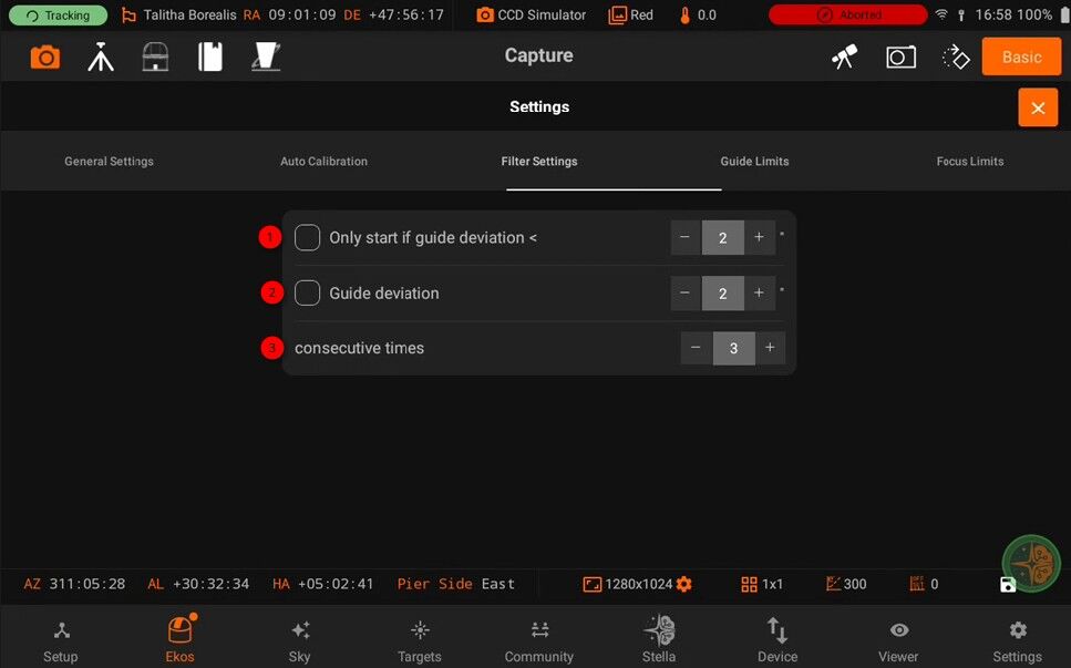
Guide limit settings are applicable to all the images in the sequence queue. When a limit is exceeded, Ekos shall command the appropriate action to remedy the situation as explained below.
Only start Guiding Deviation: Start capturing only if guide deviation is below the given threshold (ignored for previews)
Only start Guiding Deviation Value
Guide Deviation: Abort sequence if guiding deviation exceed this value N consecutive times
Guide Deviation Value
Consecutive times: Abort sequence if guiding deviation exceed this value N consecutive times
Dither per Job: If global dither is enabled, then dither every N number of frames for this job, Set to 0 to use global dither frequency.
5.3.5.4. Focus
StellarMate App Focus module goal is to get crisp images either automatically via an electronic focuser, or manually by adjusting the focus knob.
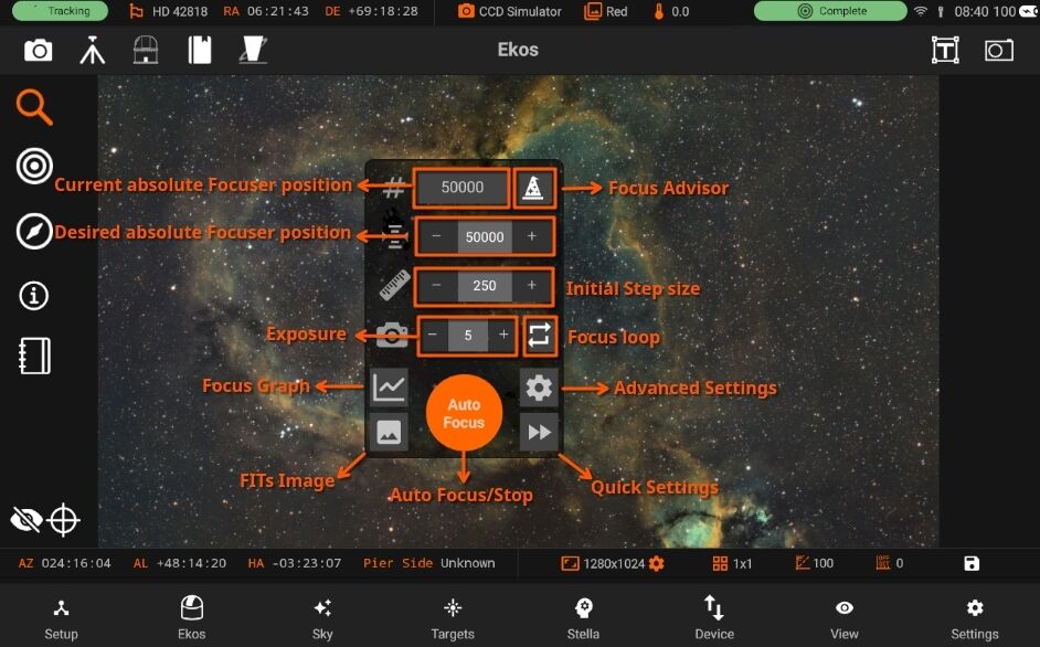
Quick Focus Guide For optimal performance, ensure the telescope is positioned near the Critical Focus Zone (CFZ). Avoid initiating autofocus when stars are barely visible or overly bloated. For reflectors, consider enabling the Donus Buster feature to address donut-shaped stars.
Before starting autofocus for the first time, run the Focus Advisor to fine-tune settings for your specific optical setup.
Absolute Focuser: While many parameters and settings play a role in a successful Autofocus run, two parameters are important to consider: Step Size: This is the value the autofocus algorithm uses to map the V-curve. Too small of a step size and it would not be able to find the minima. Conversely, very large step sizes might miss the minima. A good step size is where you notice changes in the reported HFR value by more than 0.2. Since it can be hard for some setup to estimate the optimal value, the Focus Advisor can be used to empirically measure the best step size for your particular setup. Exposure duration: Use a reasonable value of more than 1 second and less than 5 seconds. If stars are not visible by 5 seconds, try adjusting the gain.
Manual Focuser
Tap the loop icon to start the framing process. Adjust the focuser manually while monitoring the HFR values in the chart. Make gentle and slow adjustments.
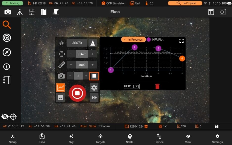
DSLR Cameras DSLR cameras like Canon and Nikon have built-in focusers. There is limited support for autofocusing using these cameras mainly due to the limited focusing capabilities.
Focuser Group All INDI-compatible focusers are supported. It is recommended to use absolute focusers for the best results since their absolute position is known on power up. In INDI, the focuser zero position is when the drawtube is fully retracted. When focusing outwards, the focuser position increases, while it decreases when focusing inwards. The following focuser types are supported:
• Absolute: Absolute Position Focusers such as RoboFocus, MoonLite, ASI ZWO
• Relative: Relative Position Focusers.
• Time Based: Time based focusers with no position feedback that adjust focus position by moving for a certain amount of time. The Focuser field contains the focuser in the attached Optical Train.
For absolute and relative focusers, the step size is in units of ticks and for simple, or time based, focusers, the step size is in milliseconds. The In and Out buttons can then be used to move the focuser by the number of ticks defined in the Initial Step Size field in the Mechanics tab.
Optical train group
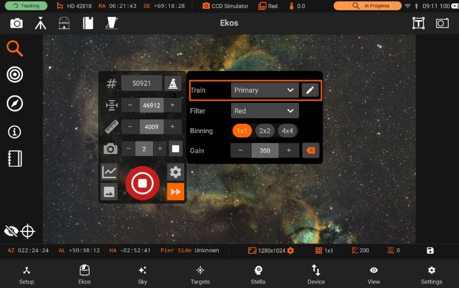
Optical Train group displays the currently selected Optical Train. By default this will be the primary imaging train, but other trains can be selected. The group consists of:
Train: The Optical Train currently in use by the Focus tab. Hover the mouse over this field for a more detailed description of the selected train. Edit Button: Brings up the Optical Train dialog to view and potentially change the optical trains. Focus parameters are saved per Optical Train automatically and so multiple trains can be setup to manage different configurations with different parameters. When a new Optical Train is created, Focus will attempt to default parameters from other, similar Optical Trains. The attributes that must match for this are the Focuser and the scope type. If this is the first train for the selected Focuser and scope type then default parameters are created.
It is recommended to use the Focus Advisor tool on new Optical Trains to set parameters appropriately.
5.3.5.4.1. Theory
In order to focus an image, StellarMate needs to establish a numerical method for gauging how good your focus is. It’s easy when you look at an image and can see it as unfocused, as the human eye is very good at detecting that, but how can StellarMate possibly know that?
The most tried and tested method is Half-Flux-Radius (HFR), which is a measure of the width in pixels counting from the center of the star until the accumulated intensity is half of the total flux of the star. As you move closer to the point of optimum focus, the HFR gets smaller, reaching a minimum at the point of focus before increasing as you start to move away from focus. HFR has been used on lots of different types of equipment and has proved to be stable in a wide range of circumstances. In addition to HFR, Ekos supports other focus measures, including an adjusted HFR measure, FWHM, Number of Stars and Fourier Power.
It is recommended to start with HFR and when the user has become proficient in focusing their equipment, to try the other measures. After Ekos processes an image, it selects either a single star and starts measuring its HFR, or it selects a set of stars matching the criteria that have been set and calculates an average HFR. It can automatically select stars, or you can select a single star manually. It is recommended to allow Ekos to select a set of stars.
5.3.5.4.2. Algorithms
Ekos supports 4 different focus algorithms: Linear 1 Pass, Linear, Iterative, Polynomial. Linear 1 Pass is the recommended algorithm.
Linear 1 Pass In the Linear 1 Pass algorithm, Ekos establishes a V-Curve and fits a curve to the data to find the focus solution. It then moves to the calculated minimum. Key features include:
The algorithm compensates for focuser backlash. The algorithm is fast, taking 1 pass to identify optimum focus. The algorithm uses more sophisticated curve fitting to pinpoint the optimum focus position. The algorithm is highly configurable with user control over many parameters like step size, number of steps and how to deal with outliers in the datapoints.
Providing the focuser behaves in a repeatable way, i.e. when commanded to go to position X, it always goes to the same position, then this algorithm will be the best to use.
Linear
In the Linear algorithm, Ekos steps outward from its starting point then moves inward taking regular datapoints through the point of optimum focus and then further inward, to draw a V-Curve. It then fits a quadratic curve to the datapoints and calculates the point of optimum focus. It then moves out again past the point of optimum focus, halves the stepsize and moves in again for a second pass. It looks to follow the curve from the first pass and find the minimum HFR. Due to randomness in the HFR measurements it uses the % tolerance to help decide when it has found a solution. Key features include: – The algorithm compensates for focuser backlash. – The algorithm is slow, taking 2 passes to identify optimum focus. – The algorithm uses curve fitting to pinpoint the optimum focus position in pass 1, but then uses % Tolerance to try to stop as close as possible to this HFR on pass 2. – The algorithm is highly configurable with user control over many parameters like step size and number of steps. If the focuser behaves in an inconsistent way, i.e. when commanded to go to position X, there is variability in the position it goes to, then this algorithm will be the best to use as it has some built in tolerance for this variability
Iterative
In the Iterative algorithm, Ekos operates iteratively by moving in discrete steps, decided initially by the user configurable step size and later by the slope of the V-Curve, to get closer to the optimal focus position where it then changes gears and performs smaller, finer moves to reach the optimal focus. The focus process stops when the measured HFR is within the configurable tolerance of the minimum recorded HFR in the process. In other words, whenever the process starts searching for a solution within a narrowly limited range, it checks if the current HFR is within % difference compared to the minimum HFR recorded, and if this condition is met then the Autofocus process is considered successful. The default value is set to 1% and is sufficient for most situations. The Step options specify the number of initial ticks the focuser has to move. If the image is severely out of focus, we set the step size high (i.e. greater than 250). On the other hand, if the focus is close to optimal focus, we set the step size to a more reasonable range (less than 50). It takes trial and error to find the best starting tick, but Ekos only uses that for the first focus motion, as all subsequent motions depend on the V-Curve slope calculations. Key features include:
The algorithm relies on the focuser having well controlled backlash. The algorithm can be fast using a minimum number of steps. The algorithm works on a “good enough” paradigm whereby it stops when the HFR is within % Tolerance of the perceived minimum. Polynomial
In the Polynomial algorithm, the process starts off in Iterative mode, but once we cross to the other side of the V-Curve (once HFR values start increasing again after decreasing for a while), then Ekos performs quadratic curve fitting to find a solution that predicts the minimum possible HFR position. Key features include:
The algorithm relies on the focuser having well controlled backlash. The algorithm can be fast using a minimum number of steps. The algorithm uses curve fitting to pinpoint the optimum focus position.
5.3.5.4.3. Advisor
The Focus Advisor dialog is a feature to assist with setting up of focus parameters. To use, select the required options and press Run. The purpose of Focus Advisor is to help people to use the Focus module within Ekos. The Focus module is functionally rich and contains a lot of parameters that need to be set self-consistently to achieve good results. Focus Advisor is designed to help with basic parameter setup that should achieve focus. It is not designed to achieve the best possible focus for your equipment; you will have to experiment with your setup to achieve that. But Focus Advisor provides a place to start that experimentation. Focus Advisor is aimed towards the less experienced users. If Focus Advisor does not appear to give good results on your setup why not start a discussion on the forum so it can be enhanced to give better results in the future. This way it will build over time to be more useful. When you click on Focus Advisor it works out a series of parameter recommendations based on the Optical Train you are using in Focus. There are 4 checkboxes on display that by default are all checked. Some can be toggled off if required. For example, Update Parameters will reset most parameters to standard settings. Once run, it is not necessary to repeatedly run this option so the associated checkbox can be toggled off for subsequent runs.
Run: Press this button to run Focus Advisor for the checked options. The V-Curve will be dynamically updated with progress, as will the Focus Advisor dialog.
Stop: Press this button to stop Focus Advisor. Note that the Stop button on the main Focus panel does the same thing.
Close: Press this button to close the Focus Advisor dialog. The following checkbox options are available:
5.3.5.4.3.1. Update Parameters
This sets the parameters in Focus Settings to standard values that should enable Autofocus to successfully complete. Note that parameters are stored per Optical Train so it is a good idea to set this option when starting. Note that some parameters, e.g. step size are better defaulted from a trial and error approach by running Autofocus. So these parameters can be better set by some other options below. Note that when a new Optical Train is created, Focus Advisor will setup default parameters when the Optical Train is used for the first time in Focus. Also note that subsequent Focus Advisor functions depend on certain parameters being selected, for example the Linear 1 Pass focus algorithm, so it is recommended to run Update Parameters at the start of using Focus Advisor.
5.3.5.4.3.2. Find Stars
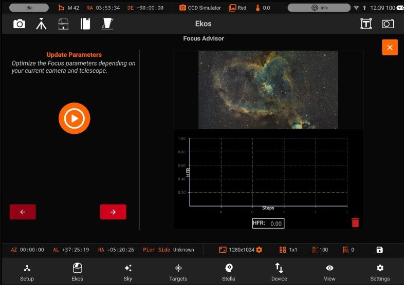
This function is designed to search the range of motion of the focuser to locate stars. If stars are already visible in subframes then there is no need to run this function. The algorithm will start at the current focuser position and search an area outward then inward of the starting position looking for stars. If no stars are found it will continue expending the search area whilst staying within the allowed range of motion of the focuser. Eventually either stars will be located or the whole range of motion of the focuser will have been searched without locating any stars. In this latter case, the step size will be halved and the search restarted from the beginning. The search process uses a series of jumps of 10 x step size to try and locate stars. To use this function start the focuser as near to where stars are likely to be found as possible. If you have no idea then the algorithm will locate stars but the search will likely take longer. In addition, use a step size as close as possible to a good value for your equipment. If a value too small is chosen then the number of steps will be larger and the search will take longer. If a value too large is chosen then its possible that the range of focus positions where stars are visible will be “jumped over” in the search and it will appear that there are no stars visible anywhere. If you have no idea what a good starting value is then use the default and let Focus Advisor try to figure it out.
The results table in the Focus Advisor dialog shows a single line for Find Stars. In this case, Find Stars was started at position 70,000 and the Step Size was 250 (giving a Jump Size of 2,500). No stars were found at 70,000 (point 1 on the V-Curve) so an outward sweep started at 95,000 and moved in 2,500 jump by jump until 70,000 was reached (points 2-11) when the inward sweep started. Stars were first detected at 60,000 (point 15). The algorithm then continues to Jump inwards until no stars are found (point 34). This gives the range of positions where stars were located as 15,000 (point 33) to 60,000 (point 15) with a centre at 37,500.
5.3.5.4.3.3. Coarse Adjustment (Without Autofocus)
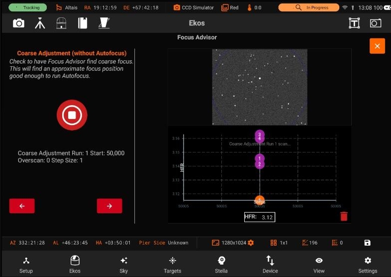
This function is designed to provide coarse adjustment to the start position, Step Size and AF Overscan (or backlash) fields. The purpose is to provide “good enough” values for these parameters in order for the next stage, Fine Adjustment to work. An iterative process is used to home in on acceptable values. Here is an example to describe how it works:
Coarse Adjustment was run from a starting position of 37,500 with a Step Size of 250 and AF Overscan of 0. This is recorded in Run 1 in the results table in the Focus Advisor dialog. The comment column says that the Max/Min Ratio = 0.9 which means that the “Max HFR” / “Min HFR” of the datapoints is 0.9 which is too low. So Focus Advisor starts Run 2 from position 38,875 with an increased Step Size of 803 and Overscan of 250. Run 2 again had a Max/Min ratio too low, so Run 3 was started. Run 3 (which is shown in the V-Curve) started from 35548 with Step Size of 2544 and Overscan of 7477. This resulted in a Max/Min of 2.0 which is good enough at this stage. The datapoints form a V-Curve with no obvious uncorrected backlash (this would show as a flat spot on the right hand side of the curve if there was any). So the Coarse Adjustment completes after Run 3.
5.3.5.4.3.4. Fine Adjustment (With Autofocus)
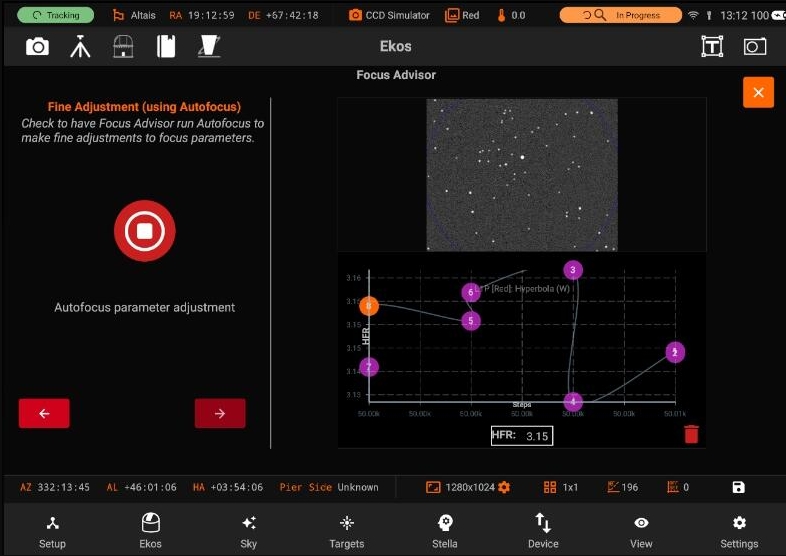
This function is designed to provide fine adjustment to the start position, Step Size and AF Overscan (or backlash) fields. Fine Adjustment runs Autofocus including curve fitting and analyses the result to determine whether or not it can be improved. If so, it adjusts parameters and re-runs. An iterative process is used to home in on parameter values. Here is an example to describe how it works:
Fine Adjustment was run from a starting position of 35,548 with a Step Size of 2544 and AF Overscan of 7477. This is recorded in Run 1 in the results table in the Focus Advisor dialog. The comment column says that the Max/Min Ratio = 1.9 which means that the “Max HFR” / “Min HFR” of the datapoints is 1.9 which could be improved. So Focus Advisor starts Run 2 from position 38,092 with an increased Step Size of 4888 and Overscan of 3738. The Overscan value is reduced here to see if a smaller number would adequately compensate backlash. Run 2 had a Max/Min ratio of 4 which is a little high, and calculated an Overscan value of 8626 so Run 3 was started. Run 3 (which is shown in the V-Curve) started from 38092 with Step Size of 4254 and Overscan of 8626. This resulted in a Max/Min of 3.1 which is good. The datapoints form a V-Curve with no obvious uncorrected backlash (this would show as a flat spot on the right hand side of the curve if there was any). The R2 of the curve fit is 0.999 which is also good so the Fine Adjustment completes after Run 3.
5.3.5.4.4. Settings
You will be able to see the Settings by pressing the Icon
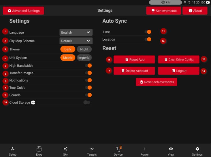
Following are the settings from Focus module: * Advanced settings * Process settings * Mechanics settings
5.3.5.4.4.1. Advanced
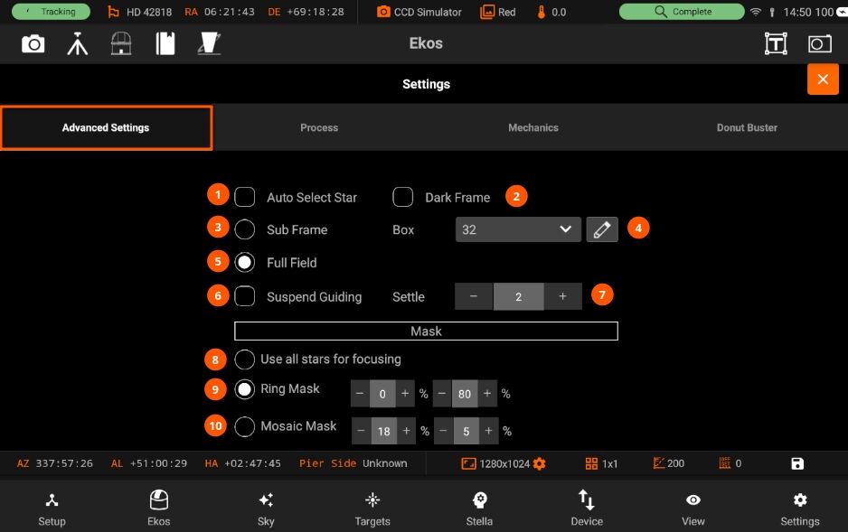
The Settings page has the following options:
Auto Select Star: Automatically detect and select best star for guiding in the image.
Dark Frame: Check this option to capture a dark frame if necessary and perform dark-frame subtraction. This option can be useful in noisy images.
Subframe: Subframe around the focus star during the autofocus procedure. Enabling subframing can significantly speed up the focus process. Box: Sets the box size used to enclose the focus star. Increase if you have very large stars.
Full field: Measure average HFR from all stars combined in a full frame. This method defaults to the Centroid detection, but can use SEP detection too. Its performance decreases as the number of stars increases.
Suspend Guiding: Suspend Guiding while autofocus in progress. If the focus process can disrupt the guide star (e.g. when using Integrated Guide Port IGP whereas the guider is physically attached to the primary CCD), then it is recommended to enable this option. When using Off-Axis guider, then this option is not necessary.
Settle: Sets the amount of seconds to wait before resuming guiding.
All stars are used for focusing.
During Full Field focusing, this controls the size of an Annulus centred at the middle of the sensor to include for processing. Set inner % to zero to include the centre of the sensor and set outer % to 100 to include the outer edges of the sensor.
Aberration inspector style mask with a 3x3 mosaic formed with tiles from the center, the corners and the edges.
Enable Adaptive Focus between subframes.This is an experimental feature. 1.Min move: The minimum size of an adaptive focus change that will be sent to the focuser.
Adapt the Autofocus start position based on filter and the Adaptive Focus settings. This is an experimental feature. 1. The maximum total Adaptive focuser movement between Autofocus runs. If this value is hit, adaptive focusing is suspended. The purpose of this control is to handle runaway adaptive focusing.
5.3.5.4.4.2. Process
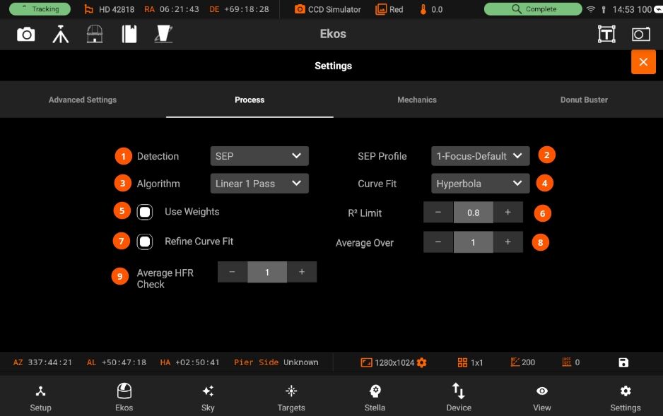
The Process page has the following options:
- 1. Detection: Select star detection algorithm. Each algorithm have its strengths and weaknesses. It is recommended to keep the default value unless it fails to properly detect stars.
SEP: Source Extractor and Photometry, an efficient source detection method based on Source Extractor (Bertin and Arnouts 1996; Bertin 2016). See SEP: Source Extractor as a library in the Journal of Open Source Software.
Centroid: a source detection based on estimating star mass around signal peaks.
Gradient: a single source detection based on the Sobel filter. Initial or full-field analysis will use SEP instead of this method.
Threshold: a single source detection based on pixel values. Initial or full-field analysis will use SEP instead of this method.
Bahtinov: This is useful for users who do not have a motorized focuser and prefer to focus manually with the aid of a Bahtinov Mask. After capturing an image in the focus module with the Bahtinov mask algorithm selected, Ekos would analyze the images and stars within it. If Ekos recognizes the Bahtinov star pattern, it will draw lines over the star pattern in circles on the center and on an offset to indicate the focus.
- 3. AlgorithmSelect the auto focus process algorithm :
Iterative: Moves focuser by discreet steps initially decided by the step size. Once a curve slope is calculated, further step sizes are calculated to reach optimal solution. The algorithm stops when the measured HFR is within percentage tolerance of the minimum HFR recorded in the procedure.
Polynomial: Starts with iterative method. Upon crossing to the other side of the V-Curve, polynomial fitting coefficients along with possible minimum solution are calculated. This algorithm can be faster than purely iterative approach given a good data set.
Linear: Samples focus inward in a regular fashion, using 2 passes. The algorithm can be slow, but it is more resilient to backlash. Start with the focuser positioned near good focus. Set Initial Step Size and Max Travel for the desired sampling interval and range around start focus position. Tolerance should be around 5%.
- 4. Curve fit: Select the type of curve to fit to the data :
Quadratic: Uses a polynomial fit of degree 2. This is currently the default option and currently the only option for all Algorithms except Linear 1 Pass.
Hyperbola: Fits a hyperbola to the data points. This is currently only available for the Linear 1 Pass Algorithm.
Parabola: Fits a parabola to the data points. This is currently only available for the Linear 1 Pass Algorithm.
5. Average over: Sets the number of frames to capture in order to average the HFR value at the current focuser position.
Tolerance: The tolerance percentage values decides when the autofocus process stops in the Iterative algorithm. During the auto focus process, HFR values are recorded, and once the focuser is close to optimal position, it starts measuring HFRs against the minimum recorded HFR in the sessions and stops whenever a measured HFR value is within % difference of the minimum recorded HFR. Decrease value to narrow optimal focus point solution radius. Increase to expand dsolution radius.
6. Use weights: Check to use the standard deviation of the star HFR or FWHM as a weighting to the curve fitting algorithm. If unchecked, all data points are given equal weighting. Currently only available when using Full Field (multiple stars) and a Curve Fit of Hyperbola or Parabola under the Linear 1 Pass algorithm.
: R2 Limit: Set a minimum for the acceptable R2 when performing an Autofocus run. The value is between 0 (no fit) and 1 (perfect fit). 0.8 is a good start. If the minimum is not met, Autofocus will rerun once to try to improve the R2. Currently only available for the Linear 1 Pass algorithm when using a Curve Fit of Hyperbola or Parabola.
7. Refine Curve Fit: Set a minimum for the acceptable R2 when performing an Autofocus run. The value is between 0 (no fit) and 1 (perfect fit). 0.8 is a good start. If the minimum is not met, Autofocus will rerun once to try to improve the R2. Currently only available for the Linear 1 Pass algorithm when using a Curve Fit of Hyperbola or Parabola.
8. Average HFR Check: No. of frames to capture when running in-sequence HFR-check. If using linear 1 pass, the point of optimum focus will also capture this number of frames.
Warning
Setting the value too low might result in repetitive loop and would most likely result in a failed autofocus process.
5.3.5.4.4.3. Mechanics
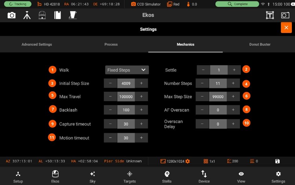
The Mechanics page has the following options:
1. Walk: Select the type for the focuser to take when using Linear 1 Pass. For Linear only Classic is available.
2. Settle: Settle time (in seconds) after moving the focuser before capturing the next image during Auto Focus and after an Adaptive focus movement.
3. Initial Step Size: In ticks to cause a noticable change in HFR value. For timer based focuser, it is the initial time in miliseconds to move the focuser inward or outward.
3. Number steps: This number is multiplied by initial-step-size is number of outward steps the Linear Focus algorithm moves away from the initial position at the start of focusing.
4. Max Travel: Maximum travel in ticks before the auto-focus process aborts.
5. Max Step size: The maximum single step size the algorithm is allowed to command as it searches for the critical focus zone. The calculated step size would be limited to this maximum value.
6. Backlash: Number of average frames to capture. During each capture, an HFR is recorded. If the instantaneous HFR value is unreliable, you can average a number of frames to increase the signal to noise ratio.
7. AF Overscan: Provides backlash overscan in ticks for outward focuser movements during an Autofocus run. This is in addition to any Driver Backlash provided by the device driver and set in the Driver Backlash field. Set to 0 to disable. If set, AF Overscan is applied to all focuser movements initiated by the Focus module. Typically either Focuser Backlash or AF Overscan is set.
8. Capture timeout: Maximum time in seconds to wait for a captured image to be received before declaring a timeout.
9. Overscan Delay: Delay between completing the outward motion of an Overscan and starting the inward motion. For most focusers 0s is fine.
10. Motion timeout: Maximum time in seconds to wait for the focuser to move to the desired position before declaring a timeout.
5.3.5.4.4.4. Donut buster
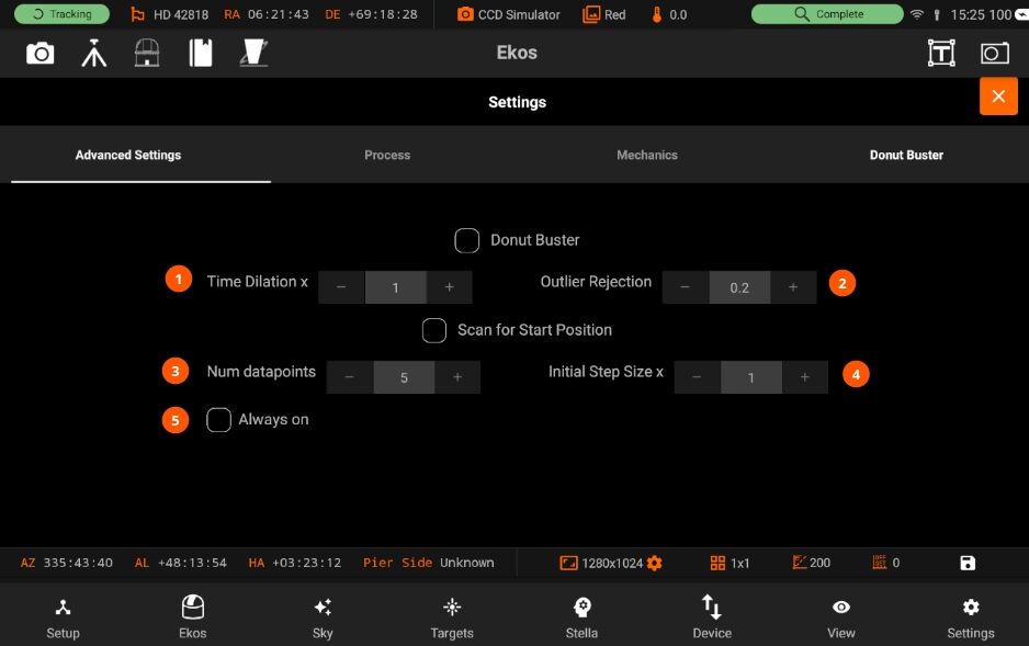
- 2. Time dilation XThe furthest datapoints have their exposure times increased by this factor. The in focus datapoint exposure is not increased. Intermediate points have their exposures scaled appropriately.
Set to 1 to disable this option.
3. Outlier Rejection: Aberration inspector style mask with a 3x3 mosaic formed with tiles from the center, the corners and the edges.
5. Num datapoints: The number of datapoints to be used during the scan for start position
6. Initial Step Size: Scan for start position uses a step size = Initial step size multiply by Initial step size x.
7. Always On: Click to always run Scan for start Position, uncheck to run after a failed Autofocus.
5.3.5.4.5. Videos
John Evans is the architect of many of the focusing algorithms used in Ekos. To learn more about the advanced features of Ekos Focus module, check out John Evans Youtube channel <https://www.youtube.com/@johneevans1>.
5.3.5.5. Mount
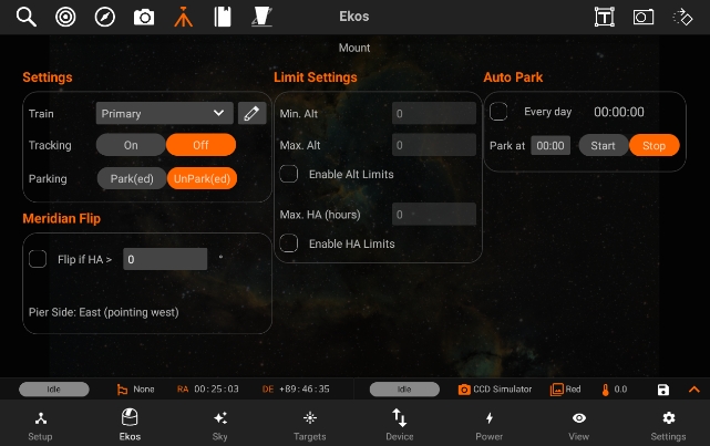
The Mount module allows you to do Meridian Flips and set limits for your Mount, it has the following features:
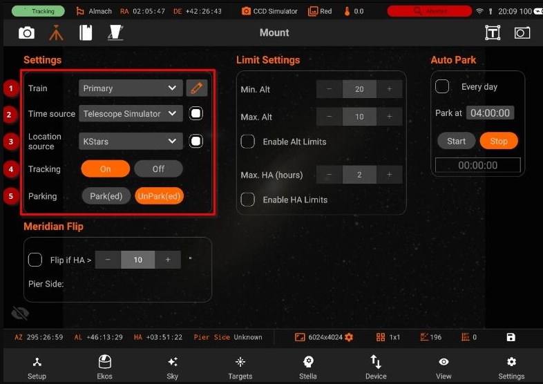
Manage / Select Optical trains.
Time source: Enable time synchronization upon connection between Kstars and INDI
Location source: Enable geographic synchonization upon connection between Kstars and INDI.
Tracking On/Off
Mount Park/UnPark
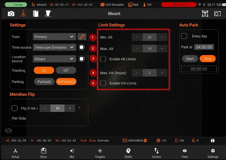
Limit Settings: * 1. Min Alt: Minimum telescope altitude limit. If the telescope is below this limit, it will be commanded to stop. * Max Alt: Maximum telescope altitude limit. If the telescope is above this limit, it will be commanded to stop. * Enable Alt limits: Enable or Disable the mount travel range limits. Once enabled, Ekos monitors the mount’s altitude while slewing or tracking. If the mount slews/tracks below or above the limits, it shall be commanded to stop and tracking will be turned off. * 2. Max Hours: Maximum Hour Angle limit if the mount has not flipped. If the telescope is above this limit, it will be commanded to stop. * Enable HA Limits: Enable or Disable the mount Hour Angle limit. Once enabled, Ekos monitors the mount’s hour angle while slewing or tracking. If the mount slews/tracks past the limit while the Pier Side is in the state that does not allow that, it shall be commanded to stop and tracking will be turned off. Requires a mount that reports the pier side correctly.
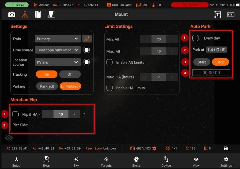
Auto Park
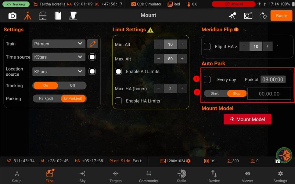
Automatically start the park timer on startup.
Park at: Park at Specific time
Whether to Start/Stop Auto Park.
Shows remaining time to Auto park
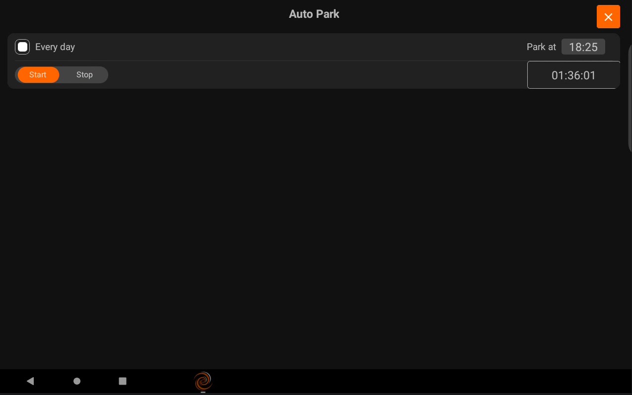
Meridian Flip
Flip if HA >: Request a meridian flip if the hour angle exceeds the specified value. Capture and Guiding will be suspended and resumed after the flip is complete.
Pier Side: Shows the pier side direction.
You can do a Meridian Flip from the Mount Module. Equatorial mounts flip after crossing the meridian in order to prevent the imaging equipment train from hitting the tripod. With Ekos, you can set an hour angle limit which if exceeded, the mount will be commended to flip. The mount must begin tracking east of the meridian in order to the meridian flip to be commanded in Ekos. When commanding a meridian flip, Ekos will suspend the auto-guiding process and waits until the mount completes the flip. Once the mount begins tracking again post meridian flip, Ekos will plate-solve and make any necessary slew commands to bring the mount to the exact location it was tracking prior to the flip. Next, it will automatically capture a frame and select a suitable guide star, performs calibration, and resumes auto-guiding. If In-Sequence focusing is enabled, it will also capture and focus a suitable star. It then resumes the capture process form where it left. All these steps are completely automated and require no user intervention! So just set when you want the meridian flip to occur at the mount module. Remember that the setting is in Hour Angle (HA). 1 HA = 15 degrees, therefore 0.1 HA = 1.5 degrees West of the Meridian. Always use a positive value to ensure proper meridian flip takes place. Using zero could theoretically work but it is at the very edge where the decision to flip or not is made by the mount, so it’s safer to use a slightly higher value like 0.1 HA.
Mount Model
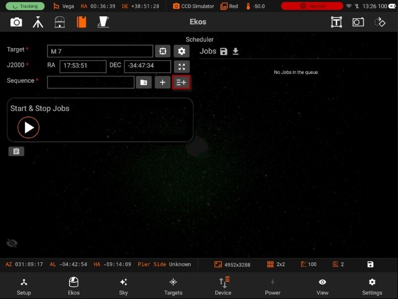
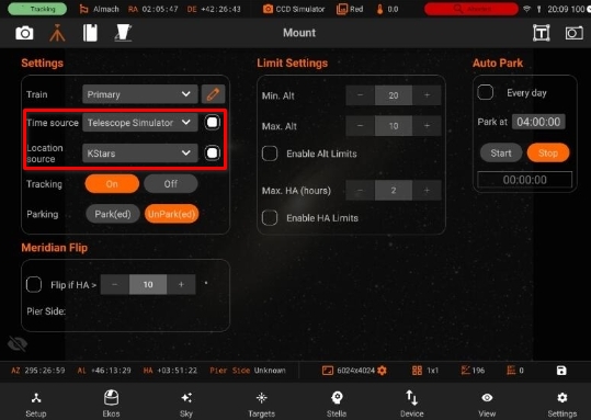
A mount model is a collection of calibration data points that describe and correct for mechanical, alignment, or optical errors in your telescope setup. These errors can be due to manufacturing tolerances, polar alignment issues, flexure, or other imperfection The mount model helps the system understand how the actual pointing of the telescope differs from its theoretical, commanded position at various points in the sky.
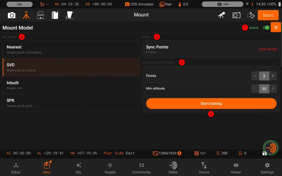
The Alignment Subsystem property turns the pointing-correction model on or off.
Math Plugins:
Nearest: picks whichever recorded sync point is geometrically closest rather than fitting a matrix model across all points; faster/simpler but less consistent, as shown in the earlier testing.
Built-in: the default plugin, used automatically if no other is explicitly loaded. It scans the alignment database and builds transformation matrices from your sync points (all RA/Dec points get converted to Alt/Az using each point’s stored timestamp before the matrices are computed).
SVD: the more robust N-star model, better at handling larger or spread-out point sets; generally the recommended choice when it’s available.
SPK: Spline interpolation, Best for Smooth, accurate points in Sky
Synced Points: are the individual data points that make up your Mount Model — each one is a record of “the mount thought it was pointing here, but it was actually pointing there”
Ability to change Points annd minimum altitude
Start training - Each successful point that is plate solved adds up one sync point.
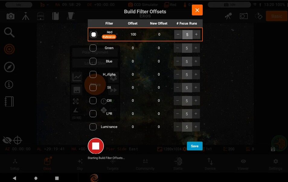
5.3.5.6. Observatory
The Observatory module allows you to control your Dust Cap, Light Box and Dome/Roll-off roof, it has the following features:
Dome & Rolloff Roof
StellarMate supports both classical domes and rolloff roofs. For rolloff roofs, the only controls available are the Park and Unpark actions.
Park/UnPark Park: Moves the dome to its home position. Always park when finishing observations.
UnPark: Releases the dome from its parked position. Use this command to enable dome movement and rotation control during your observation session.
Classical domes support more features like dome slaving and controls for shutter and azimuth.
Slaving
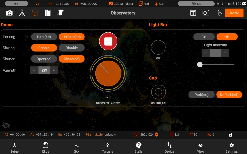
Dome slaving automatically synchronizes your dome’s azimuth position with the telescope’s pointing direction. This ensures the telescope always has an unobstructed view through the dome’s slit or opening during observation and imaging sessions. Achieving accurate and reliable slaving requires careful measurement of your observatory’s geometry and understanding key configuration parameters.
All geometric measurements should be provided in meters. These parameters are typically found in the INDI Control Panel under your Dome Driver’s Slaving tab within the Measurements group.
Geometric Measurements
Radius (m): The internal radius of the dome, measured from the exact center of the dome floor to the inner surface of the dome wall.
Shutter width (m): The clear, unobstructed width of the dome’s shutter opening. While currently used to calculate a theoretical minimum/maximum azimuth range for the opening, this parameter is primarily intended for future optimizations to minimize unnecessary dome movements during slews. The core slaving calculation targets the center of this opening based on the optical axis intersection.
N displacement (m): The North/South displacement of the telescope’s mount pivot point (intersection of RA and Dec axes for GEMs, or Az/Alt axes for Alt-Az mounts) from the exact center of the dome floor.
Positive values: Displacement towards the North.
Negative values: Displacement towards the South.
E displacement (m): The East/West displacement of the telescope’s mount pivot point from the exact center of the dome floor.
Positive values: Displacement towards the East.
Negative values: Displacement towards the West.
Up displacement (m): The vertical displacement (height) of the telescope’s mount pivot point relative to the level of the dome’s base ring (the equator of the dome sphere).
Positive values: Pivot point is above the dome equator.
Negative values: Pivot point is below the dome equator.
OTA offset (m): The perpendicular distance between the telescope’s optical tube axis (OTA) and the mount’s pivot point (RA/Dec intersection for GEMs).
Fork Mounts: This value is typically zero as the optical axis usually passes through the pivot point.
German Equatorial Mounts (GEMs): This is a critical non-zero value representing the distance from the RA/Dec intersection point to the center line of the telescope tube. It accounts for the offset caused by the mount’s design.
Slaving Parameters
Autosync threshold (deg): (Found under the Params property group)
This defines the minimum difference in degrees between the dome’s current azimuth and the calculated target azimuth required to trigger an automatic dome movement (sync).
The default value is typically 0.5 degrees.
Smaller values: Result in more frequent, smaller dome movements, keeping the slit very precisely aligned but potentially causing more wear or vibration.
Larger values: Result in less frequent, larger dome movements, reducing wear but potentially allowing the telescope’s view to drift slightly off the slit center between moves. Choose a value that balances alignment accuracy with minimizing unnecessary motion for your setup.
Meridian side: (Found under the Meridian side property group)
This parameter is crucial, especially for German Equatorial Mounts (GEMs), as it tells the slaving algorithm which side of the pier the telescope tube (OTA) is currently situated. This directly affects the calculation of the optical axis position relative to the dome center.
Available Options:
East / West: Manually forces the calculation to assume the OTA is on the specified side of the pier. Use only if the automatic methods fail or for specific testing.
Mount: (Recommended for most GEMs) Uses the pier side information directly reported by the connected INDI mount driver. This is generally the most reliable option if your mount driver supports and correctly reports pier side.
Hour Angle: Calculates the pier side based on the telescope’s Hour Angle (HA). It assumes HA > 0 (pointing West) means the OTA is East, and HA < 0 (pointing East) means the OTA is West. Note: When pointing very close to the celestial pole (typically Declination > +/- 85 degrees), where HA becomes less reliable for side determination, this mode intelligently uses the telescope’s Azimuth instead (Az < 90 or > 270 implies OTA West, Az between 90 and 270 implies OTA East) to infer the side.
Ignore: Assumes the OTA offset is effectively zero relative to the pier, as in a Fork or Alt-Az mount configuration. Select this for non-GEM mounts.
Troubleshooting & Tips
Inaccurate Slaving: Double-check all geometric measurements under the Measurements group. Small errors, especially in displacements and OTA offset, can lead to significant pointing inaccuracies. Ensure units are correct (meters).
Incorrect GEM Behavior: Verify the Meridian side setting. Using Mount is preferred if your mount reports pier side correctly. If not, Hour Angle is a good alternative. Incorrect settings here are a common cause of slaving errors after a meridian flip.
Dome Moves Too Often/Not Often Enough: Adjust the Autosync threshold (deg).
Check Logs: Enable verbose logging for the dome and mount drivers in INDI Control Panel to see detailed coordinate information, calculated target azimuths, and potential error messages. This is invaluable for diagnosing issues. Look for logs related to GetTargetAz, UpdateMountCoords, and UpdateAutoSync in the dome driver logs.
Shutter
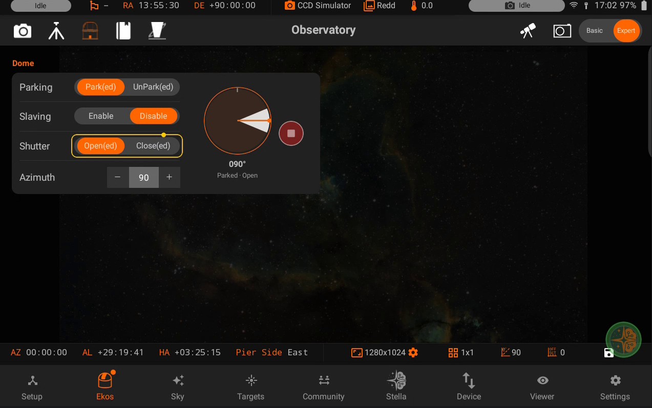
Open: Open the dome shutter to provide telescope access to the sky for observation.
Close: Close the dome shutter to shield your equipment from environmental elements when not in use.
Azimuth
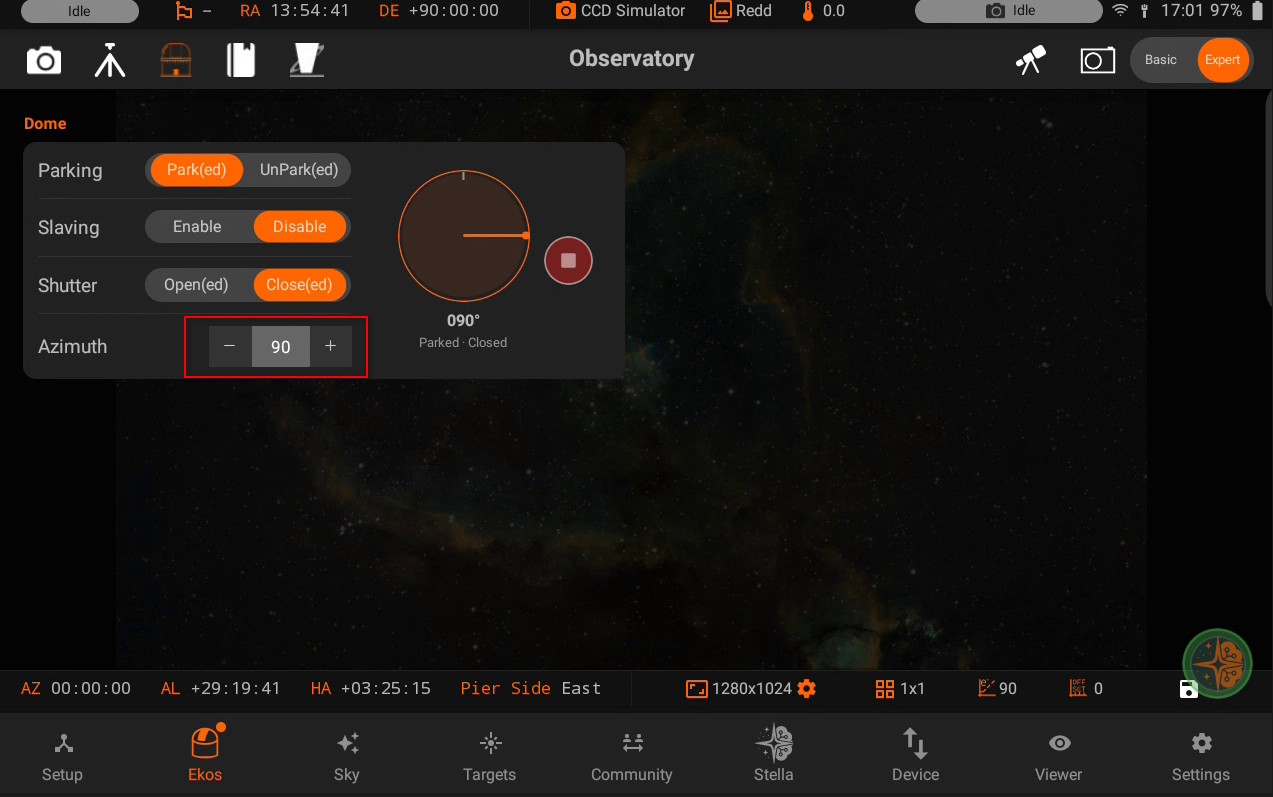
Set the dome’s rotational position using the numerical value control. Input a value between 0° and 359° to precisely align the dome slit with your telescope’s pointing direction. Adjust this value whenever you need to reposition the dome during your observation session.
Abort
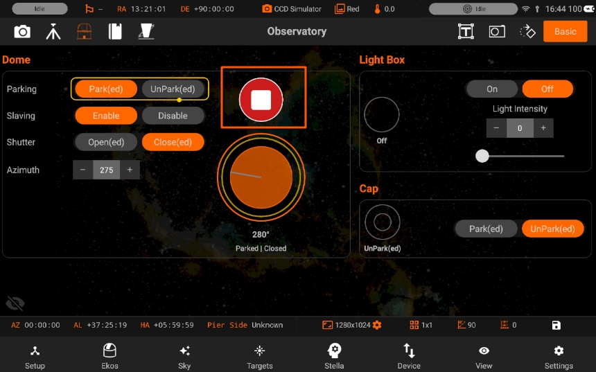
Stop operation: Halts all dome movement immediately. Use to stop rotation, parking/unparking, or shutter operations in progress.
Light Box
Enable: Turns on the light box for illumination.
Disable: Turns off the light box.
Light Intensity - Adjust the brightness of your light box using the slider control. Move the slider to the right to increase illumination intensity. Move the slider to the left to decrease illumination intensity.
Dust Cap
Park: Close the dust cap to protect optical elements when not observing. Unpark: Open the dust cap to allow light to enter the telescope during observation.
5.3.5.7. INDI Control Panel
INDI Control Panel provides an interface to interact with the drivers of the devices connected to Stellarmate. It is a front-end for the INDI controls available on KStars.
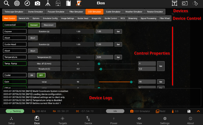
- The connected devices are show at the top :
Selecting one will show it’s control groups
Selecting one of the control groups displays it’s properties in
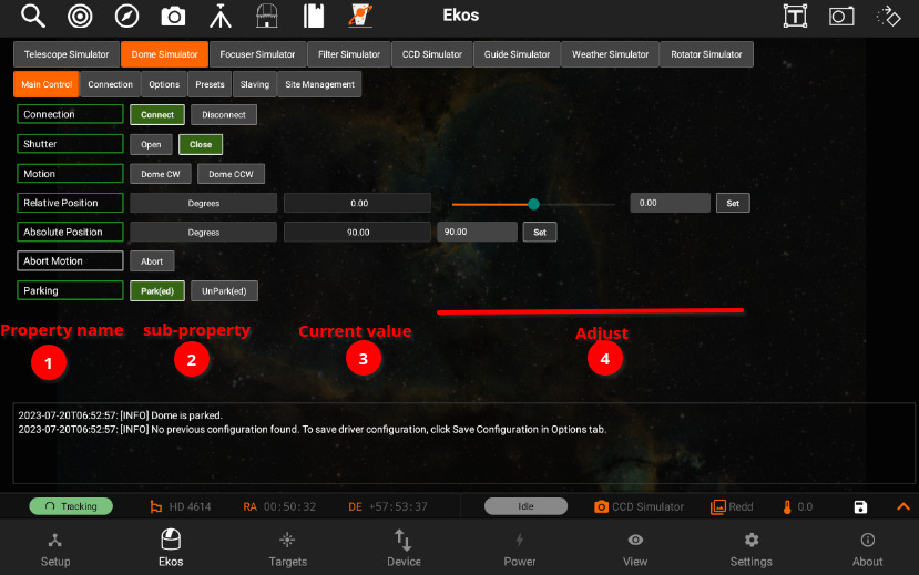
- Each property :
can have multiple sub-properties
The current value for the sub-property is shown at
The status of the property (1) would change from gray (idle) to green (successful), red (failed) or yellow (in-progress) when any changes have been set.
Some properties allow values to be adjusted. They can be changed using text field (and sometimes a slider for some number properties), and once you are done changing a property, you press Set (5) to send the new property settings to the corresponding device, to change the value.
Some properties are read only and cannot be changed.
Some buttons show the active button (1), and a different button can be set active simply by pressing it. Other buttons (2) only send the action once pressed and we can tell if it was successful from the property status (3).
5.3.5.8. Scheduler
Ekos Scheduler is an indispensable arsenal in building your robotic observatory. A Robotic observatory is an observatory composed of several subsystems that are orchestrated together to achieve a set of scientific objectives without direct human intervention. It’s recommended to use Ekos Scheduler after you are familiar with using all the Ekos modules manually first. Fine-tune the settings for each module to suit your particular equipment setup.
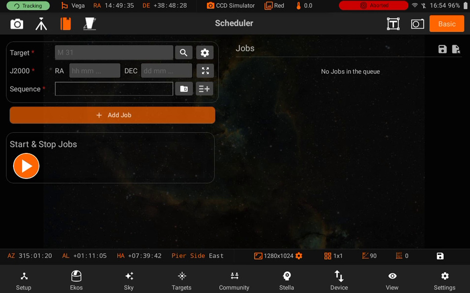
Ekos Scheduler provides a simple interface to aid the user in setting the conditions and constraints required for an observation job. To add a new scheduler task, or job as it is called in Ekos, you need to select the following: To add a new scheduler task, or job as it is called in Ekos, you need to select the following:
Target: Target can be selected directly by tapping on the Select Target button or by finding a target in the Targets module and then tapping Schedule while Ekos is in offline mode.
Sequence: A sequence file describes the required settings for each batch of images. Create a sequence file in the Capture module and save it for later.
Steps: Each job goes through a sequence of discrete steps. Each step or stage can be toggled on or off as desired: a. Track: Mount is commanded to slew to target. b. Focus: Camera auto-focus (if applicable) is started. c. Align: Plate-solving is performed to ensure the correct location, framing and orientation of the target is met. If a FITS file is specified in General Settings, then this file is first plate-solved and then mount is commanded to to slew to target solution coordinates. This is followed by another plate-solving process to ensure we are within tolerance at the target solution coordinates. If the position angle of the FITS image is different from the current camera orientation, the camera orientation can be automatically adjusted if a mechanized rotator is detected. Otherwise, a manual camera rotation is required until the image position angle is satisfied. d. Guide: Using a guide camera, the mount tracking is locked to a guide star to enable long-exposure astrophotography
After the first 4 stages are complete, the sequence file is loaded in the capture module and batch capture commences. All images are saved to storage and can be accessed in the View tab. For EkosLive Pro subscribers, all images are also uploaded to the cloud storage if StellarMate is connected to the internet.
5.3.5.8.1. Jobs
You must select the Target and Sequence before you can add a job to the Scheduler. When the scheduler starts, it evaluates all jobs in accord to the conditions and constraints specified and attempts to select the best job to execute. Selection of the job depends on a simple heuristic algorithm that scores each job given the conditions and constraints, each of which is weighted accordingly.
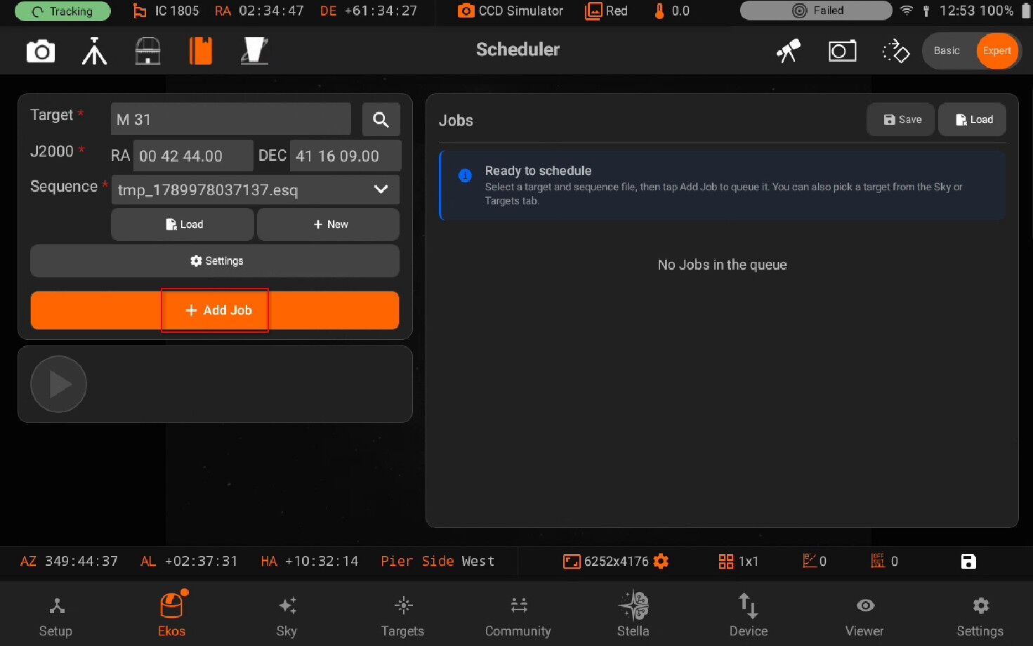
Target can be selected by pressing on the search button
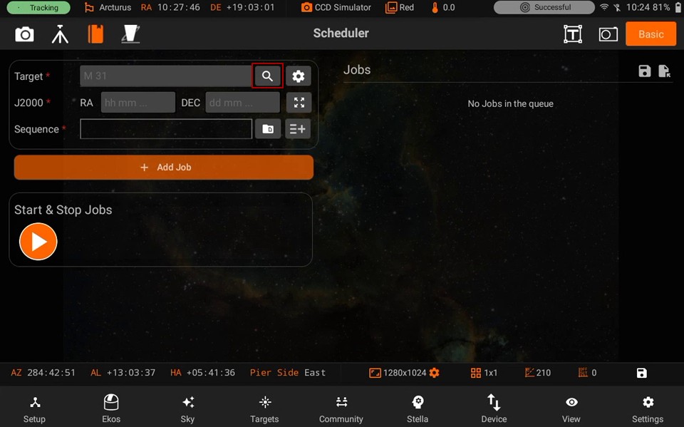
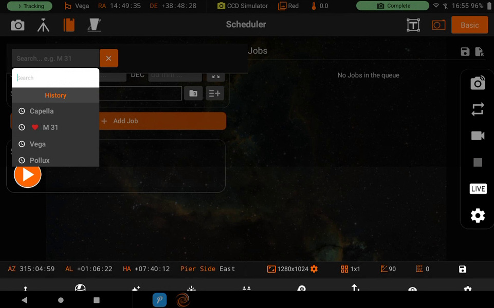
You can press on the Add button to Add a Scheduler Job. Jobs are on the right side of the screen.
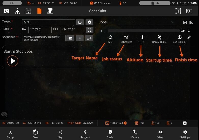
- Above, you can see the details of the Job. Its specifies the following:
Name of the Target object
Current Status of the Job
Altitude in degrees
Starting time of the Job
Completion time of the Job
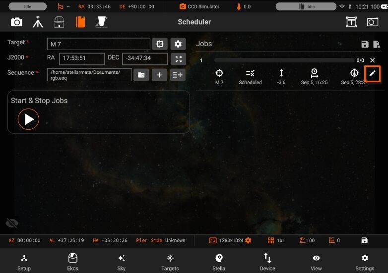
Edit a Job when it is not running.
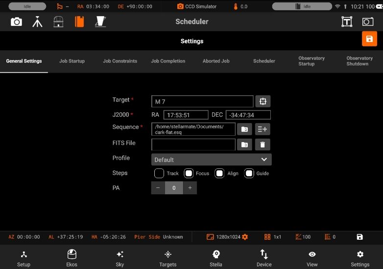
Target, Sequence and all other settings can be updated.
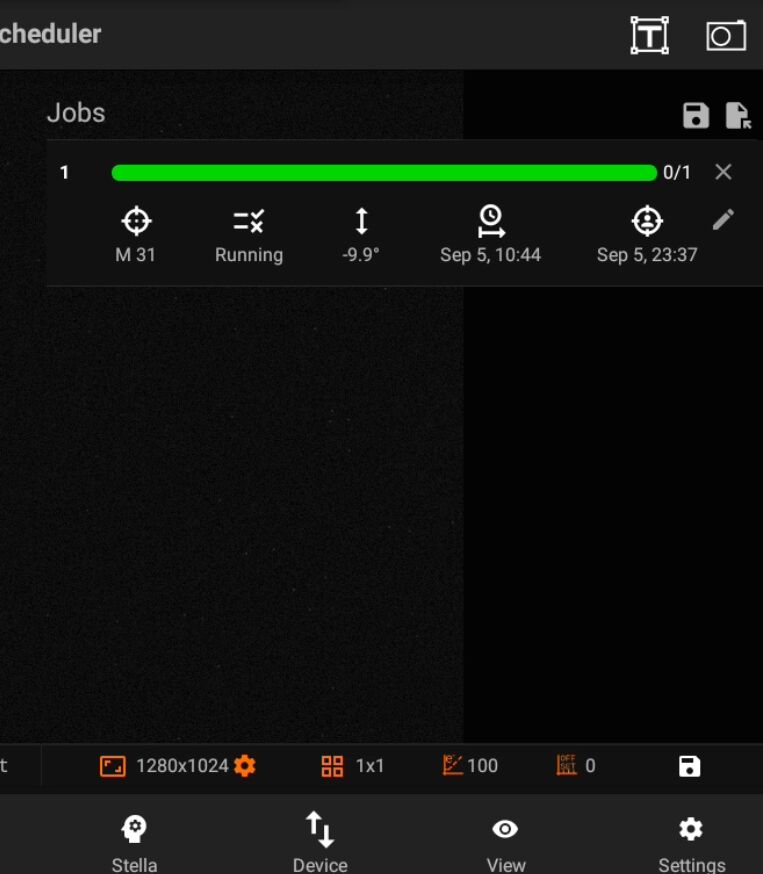
Once the Job is completed, the linear progress is turned to green and Job status is also updated when it is completed.
5.3.5.8.2. Settings
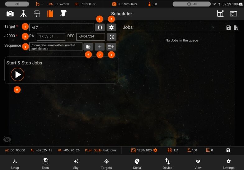
Target name: Target designation is automatically filled. It can be adjusted manually..
Target Selector: Search Targets can be also selected from the Targets tab when Ekos is offline.
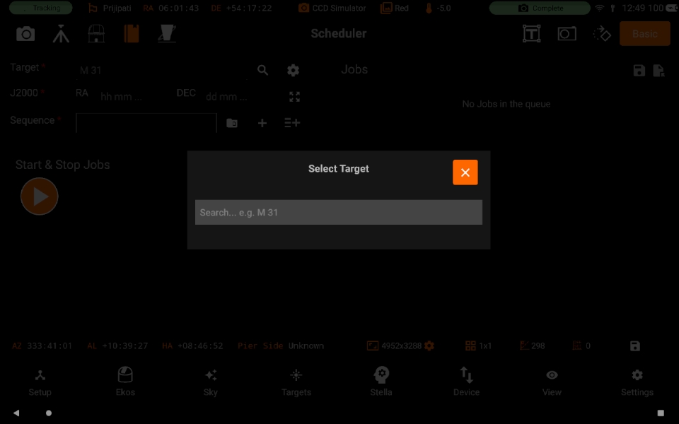
J2000: RA and DEC are displayed of a specific target. You can also manually enter the desired coordinates.
Sequence File: Sequence: A sequence file describes the required settings for each batch of images. Create a sequence file in the Capture module and save it for later.
Load: Load a sequence file.
New: Add a standalone sequence
Settings: Contains all of the settings of Scheduler module.
Add Job: Add a Scheduler Job
General Settings:
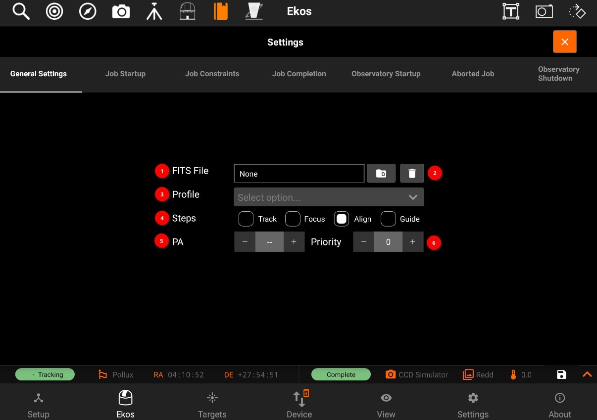
Optional FITS file: If a FITS file is specified, the astrometry solver shall solve the file and use the central RA/DEC as the target coordinates. You can select the file using Directory browser. Removes selected FITS file.
Profile: Select which equipment profile to utilize when starting Ekos. If Ekos & INDI are already started and online, this selection is ignored.
Steps: Each job goes through a sequence of discrete steps. Each step or stage can be toggled on or off as desired:
Track: Mount is commanded to slew to target.
Focus: Camera auto-focus (if applicable) is started.
Align: Plate-solving is performed to ensure the correct location, framing and orientation of the target is met. If a FITS file is specified in General Settings, then this file is first plate-solved and then mount is commanded to to slew to target solution coordinates. This is followed by another plate-solving process to ensure we are within tolerance at the target solution coordinates. If the position angle of the FITS image is different from the current camera orientation, the camera orientation can be automatically adjusted if a mechanized rotator is detected. Otherwise, a manual camera rotation is required until the image position angle is satisfied.
Guide: Using a guide camera, the mount tracking is locked to a guide star to enable long-exposure astrophotography
Position Angle: Select the desired Sky Position Angle in degrees (East of North). Ignore this setting to image using the camera current position angle. Use Target tab Framing Assistant tool to visually adjust the field of view until the desired orientation is achieved.on angle: You can also specify and position angle.
Job Startup
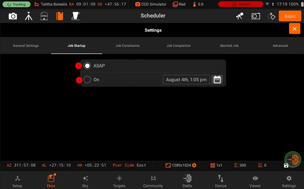
ASAP: Start the observation job as soon as all the constraints, if any, are met. The best candidate target shall be imaged first.
ON: Start the job on the specified date and time.
Job Constraints:
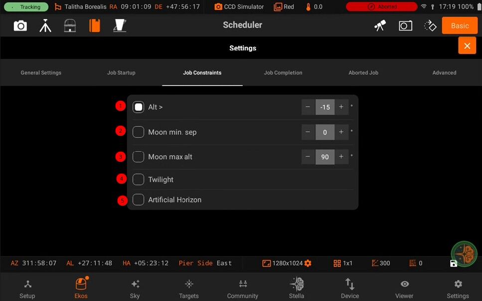
Alt: The object’s altitude must remain equal or higher than the given value.
Moon: The moon separation must remain equal to or higher than the given value.
Weather: Weather conditions must remain safe. When weather conditions become dangerous, shutdown procedure is initiated.
Twilight: The twilight restriction constraints jobs to execute in astronomical darkness. Use the dusk and dawn offsets in the Ekos Scheduler options to adjust the interval.
Artificial Horizon: The A.H restriction constrains the attitude of the target to be above the artificial horizon. If any are defined and enabled. See the artificial horizon item in the KStars Settings menu.
Job Completion:
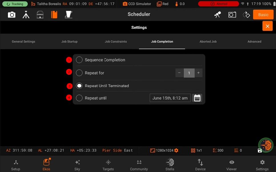
Sequence Completion: The observation job is completed when the sequence is complete.
Repeat for: No. of times sequence will repeat.
Repeat until terminated: Restart the sequence job indefinitely.
Repeat until: Terminate the job on given date and time.
Aborted Job:
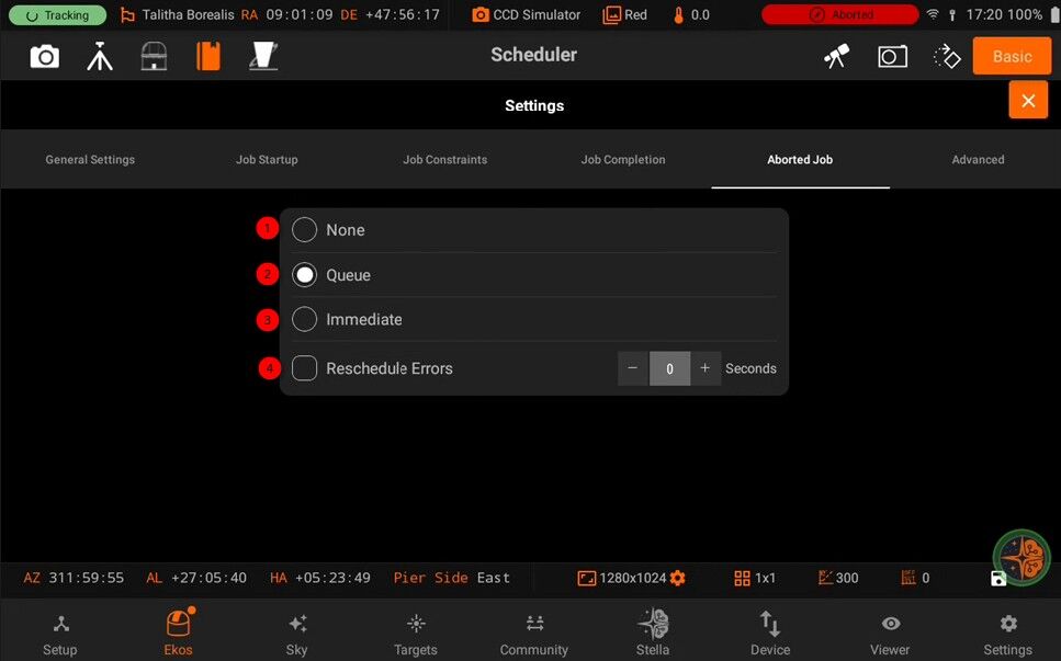
None: Do not reschedule aborted jobs. Queue: Reschedule aborted jobs as soon as all executable jobs are either completed or aborted. Immediate: Reschedule an aborted job immediately. Reschedule errors: Treat errors like aborts. (Delay in seconds).
Scheduler
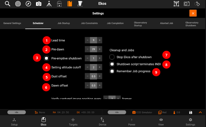
Lead time is the minimum time in minutes between jobs. The scheduler starts execution of a job before its scheduled startup time by this lead time. Early execution is useful as focusing, alignment, and guiding procedures may take prolonged periods to time to complete.
Do not permit jobs to be scheduled or executed past this many minutes before dawn.
In case no scheduler job is scheduled for this many hours, perform a complete shutdown procedure and restart observatory operations once the next job is ready.
Enable Weather-Based Scheduling: Prevents new jobs from starting during weather warnings or alerts. Existing jobs continue during warnings, but are aborted during alerts. System initiates a soft shutdown and waits for improved conditions or grace period expiration, after which the current job is terminated.
Do not permit jobs to be scheduled less than this many degrees before the altitude restriction. Actual execution proceeds until the altitude limit.
Offset astronomical dusk by this many hours. This positive or negative value adjusts the twilight restriction.
Offset astronomical dawn by this many hours. This positive or negative value adjusts the twilight restriction.
After shutdown procedure is successfully executed, stop INDI and Ekos.
If the shutdown script terminates INDI server, enable this option so that no disconnection errors are generated.
When processing a scheduled job, resume the sequence starting from the last image present in storage.
When checked the Scheduler tries to run lower priority jobs when no higher priority job can run. Recommended
Warm up the Camera sensor before shutting it down.
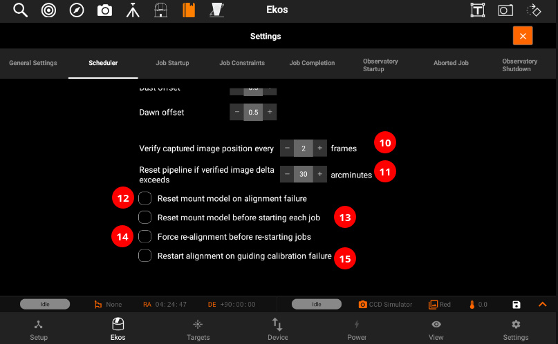
When calculating position after captures, compute it every Nth capture. Set to 0 to disable.
If captured position exceeds target position by more this many arcminutes, abort capture and reschedule the pipeline.
Reset mount model on alignment failure
Reset mount model before starting each job
If Align is enabled, scheduler would initiate a realignment procedure before restarting any jobs even if guiding is active.
If guiding calibration fails then restart alignment process before proceeding to guiding recalibration process again. This can help recenter the target object in the field of view if the calibration process strayed too far off.
5.3.5.8.3. Standalone Sequences
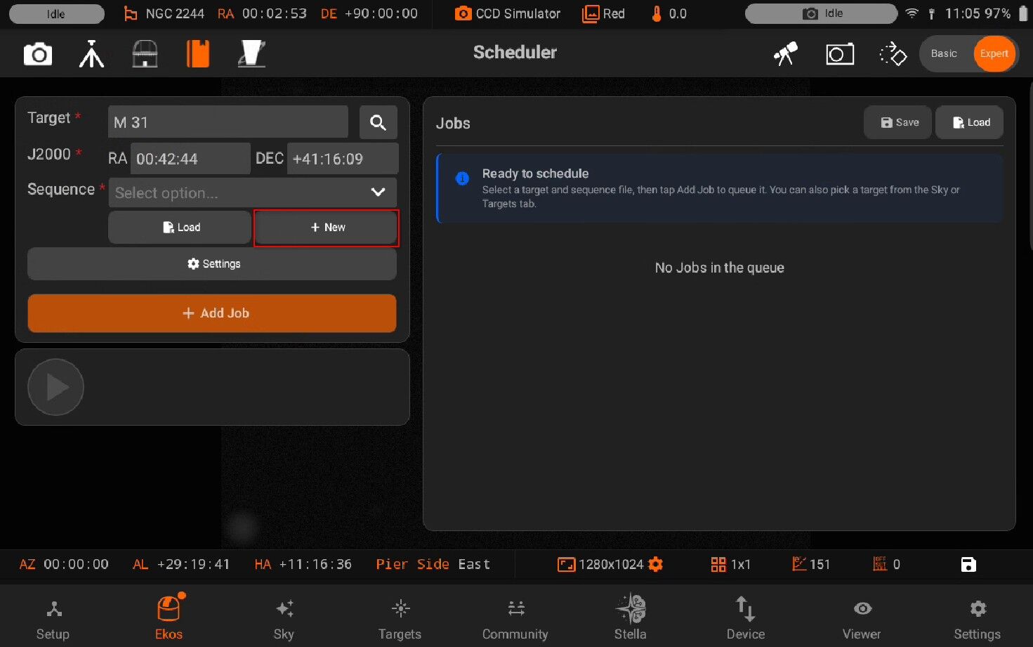
At minimum, a scheduler job requires a target and a sequence file. The sequence files contain the sequence jobs that need to be carried out in the capture module (e.g. capture 60x15 LRGB images). You can create and save sequence files in the capture module. They are saved to Documents/sequence folder so they can be reused in the future.
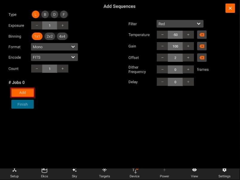
Alternatively, you can generate sequences on the spot with the Standalone Sequence editor. If Ekos is online, the editor will be based on the values of your current setup (e.g. filter list). On the other hand, if Ekos is not started yet, it will rely on settings from your previous session. You can add as many jobs as desired. When done, a sequence file is generated and automatically saved to the sequences folder.
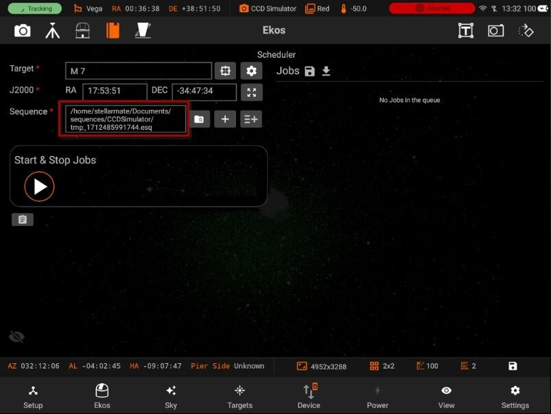
5.3.5.8.4. Data acquisition
The overall procedure typically utilized in an observatory can be summarized in three primary stages:
Startup
Data Acquisition (including pre-processing and storage)
Shutdown
Ekos Scheduler only initiates the startup procedure once the startup time for the first observation job is close (default lead time is 5 minutes before startup time). Once the startup procedure is completed successfully, the scheduler picks the observation job target and starts the sequence process. If a startup script is specified, it shall be executed first.
Data acquisition
Depending the on the user selection, the typical workflow proceeds as following:
Slew mount to target. If a FITS file was specified, it first solves the files and slew to the file coordinates.
Auto-focus target. The auto-focus process automatically selects the best star in the frame and runs the auto-focus algorithm against it.
Perform plate solving, sync mount, and slew to target coordinates.
Perform post-alignment focusing since the frame might have moved during the plate solving process.
Perform calibration and start auto-guiding: The calibration process automatically selects the best guide star, performs calibration, and starts the auto-guide process.
Load the sequence file in the Capture module and start the imaging process.
5.3.6. Data Storage
Formats
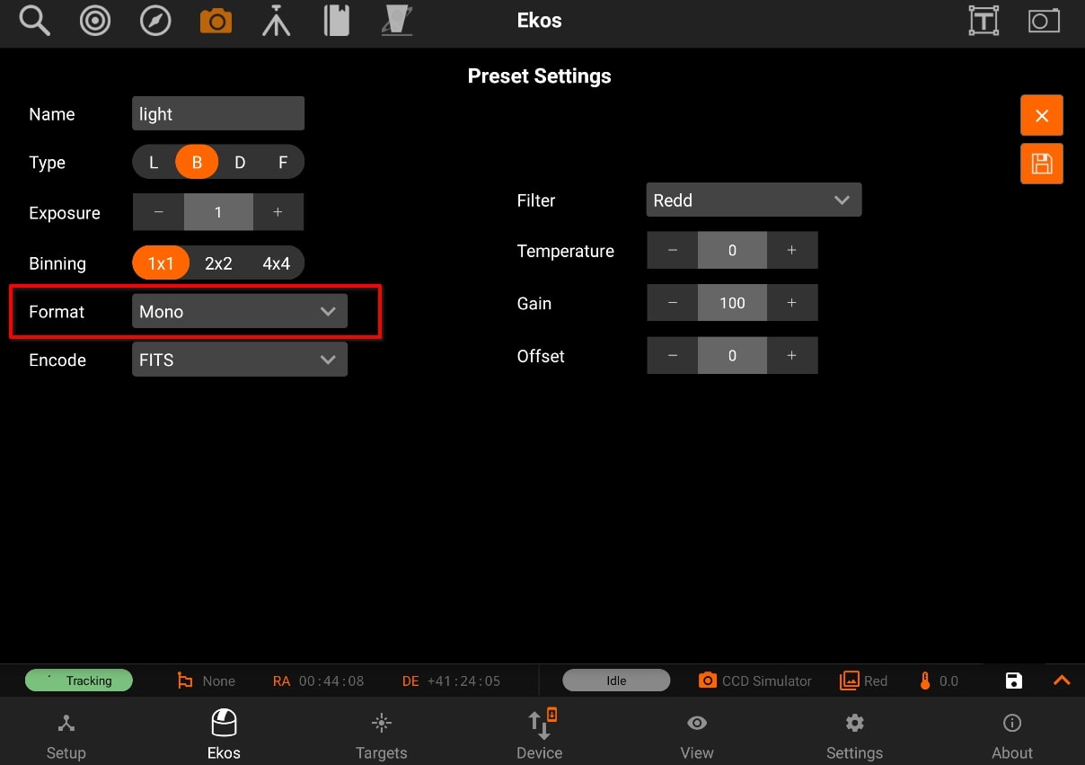
By default, all captured images are saved as FITS (Flexible Image Transport System) files. FITS is the standard image format for astronomical images and is supported by all astronomical image processing software. For DSLR cameras, saving RAW images directly (e.g. CR2) is also supported by editing the DSLR camera capture preset. Depending on the camera settings and support, images can be captured as Mono, RAW, or RGB.
- Mono:
Monochromatic single channel images store only intensity information in either 8bit or 16bit. Camera sensors generating 10bit or 12bit data are stored as 16bit by padding zeros, they are not up-scaled or modified.
- RAW:
Color cameras with a Bayer filter often support RAW8 or RAW16 formats. The bayer pattern (e.g. RGGB) depends on the camera model. StellarMate saves the RAW images as is, but debayers them for display purposes. RAW format is the recommended format for color cameras.
- RGB:
Color cameras can export a three channel RGB24 (8 bit per channel) or RGB48 (16 bit per channel) if supported by the camera sensors. Usually, the RGB output is generated by an internal debayer mechanism in the camera firmware. Files tend to be larger in size compared to RAW images but do not require any debayering.
Capture modes:
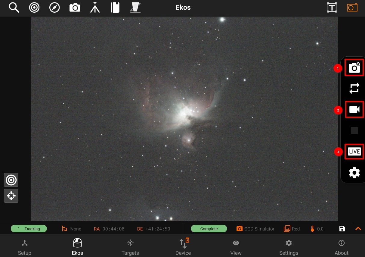
1. Previews Preview images captured using Quick Camera Control are not saved to the internal StellarMate storage.
- Sequences
Sequence images captured in the Capture Module are saved to default storage location on StellarMate internal storage. The default full directory path is /home/stellarmate/Pictures.
The Pictures directory can be changed in the Capture Module File Settings. If an external storage (e.g. SSD) is detected, you can select it as the default storage location.
All sequence images are saved along with their metadata and can be viewed in the View tab.
Live Stacking
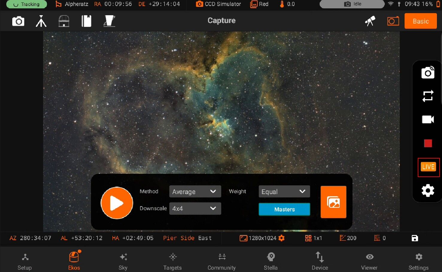
Live Stacked images are automatically saved to /home/stellarmate/Pictures/livestacking and are also available in the View tab.
If a sequence is already in progress, then live stacking starts when the next sequence image is captured. When no sequences are in progress, StellarMate starts capturing images continuously (looping) as per the settings in the Camera Quick Settings.
After each image is captured, it is then live-stacked and the generated output is displayed sequentially in the thumbnail carousel.
4. Video If supported by the camera, video streams can be saved to the internal storage by clicking on the Video icon in Camera Quick Control. By default, video files are stored under /home/stellarmate/indi_D where D designates the date.
1. SER Save streaming images in SER lossless format. Beware that this can consume storage space very quickly. To view the video, you need to export the SER video file to a PC/Mac and open it using an SER player.
2. OGV Ogg Theora is a free and open lossy video compression format that sacrifices image quality to decrease storage space. To view the video, you need to export it to a PC/Mac and use a video player with support for Ogg Theora format.
Exporting to Phone/Tablet storage
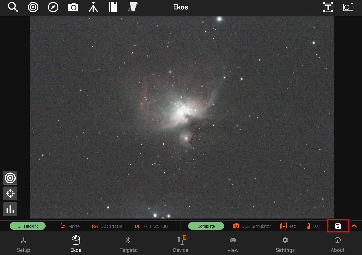
Any images displayed in the main image view can be exported to phone/tablet storage by clicking on the save icon on the camera status bar. It is saved as a time-stamped JPG image.
Exporting to PC/Mac
If you captured images and saved them to StellarMate, then they should be available by default under /home/stellarmate/Pictures. To access the images over the network, there are two options:
On Windows, click on the Network icon in the left pane of File Explorer as illustrated below.
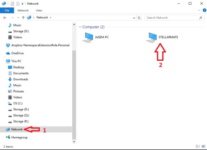
On Linux & MacOS: Use FileZilla to connect to StellarMate via Secure FTP (sftp) using your username (stellarmate) and password (smate). Remember to set port to 5624.
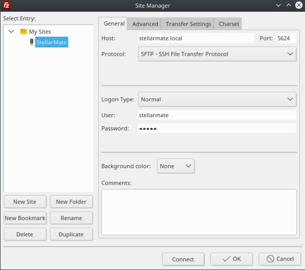
5.3.7. Directory Browser
Directory browser
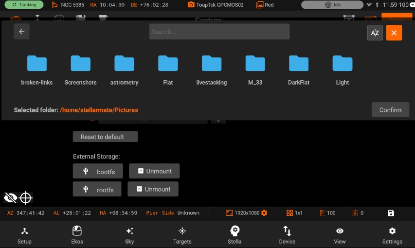
You can now choose files i.e Script file, Sequence file, fits file etc. Directory browser will extract the path from Stellarmate dolphin and set it according to the requirement input. We are using Directory browser on different places.
Scheduler:
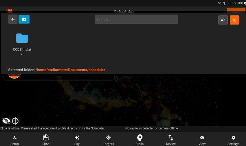
While selecting the sequence file or .fits file for Scheduler, we use Directory browser.
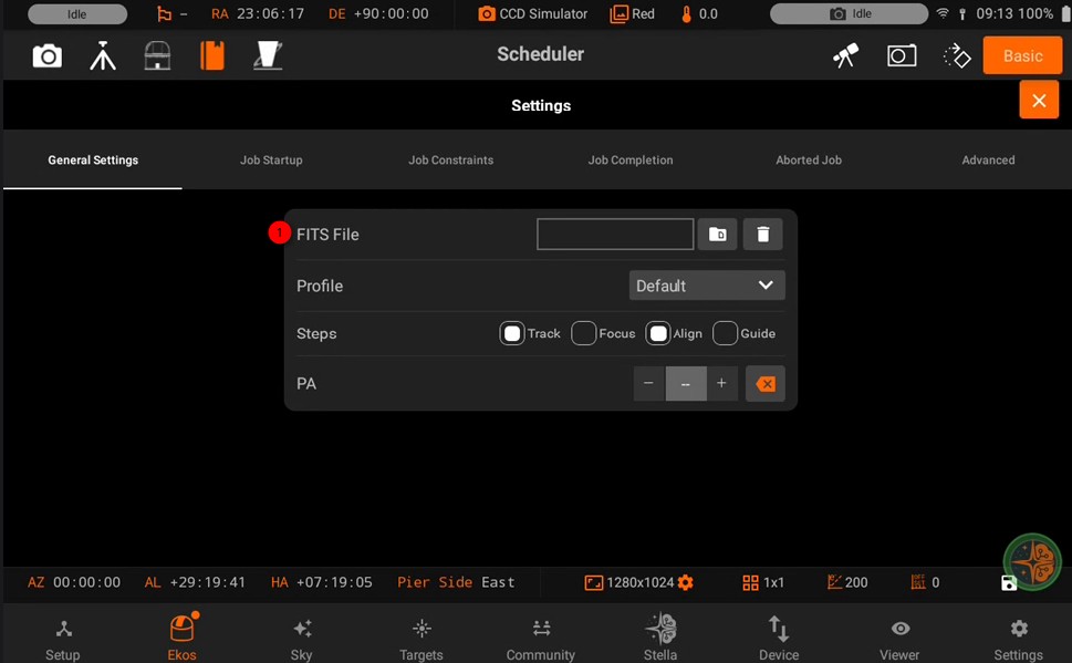
Path:
It is also used to set path for images in File Settings & recording settings using Directory browser.
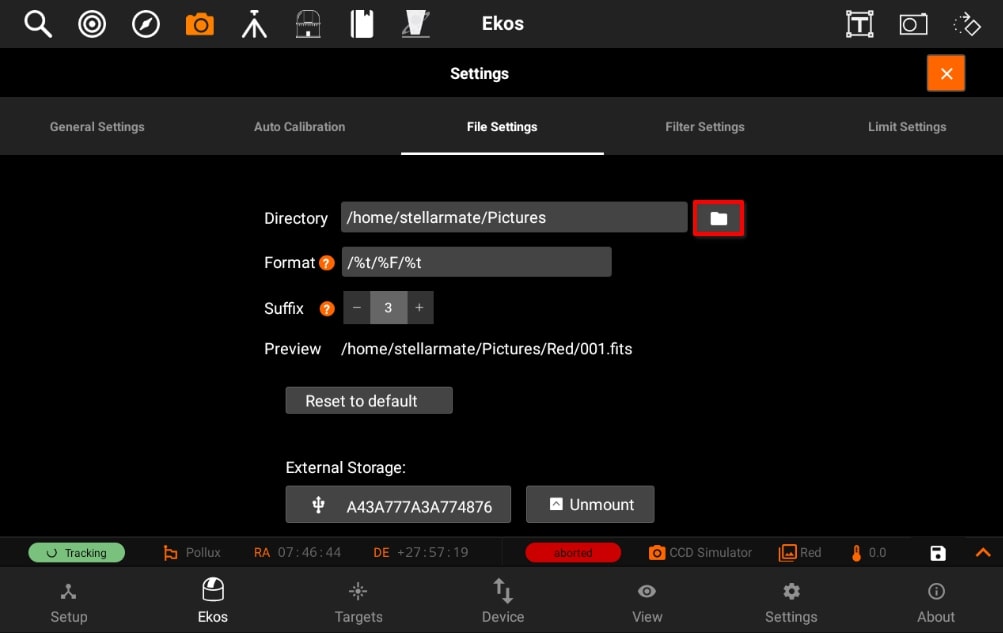
You can also create directories via Directory browser.
5.4. Sky Map
The Sky Map tool provides an interactive all-sky planetarium view within the StellarMate App. It includes multiple toggleable layers for solar system objects, stars up to 12th magnitude, galaxies, nebulae, and star clusters.
To track an object, double-tap it. An orange crosshair indicates the object is being tracked. Once tracked, you can zoom in and out without losing track of the object. To exit track mode, tap anywhere else on the sky map.
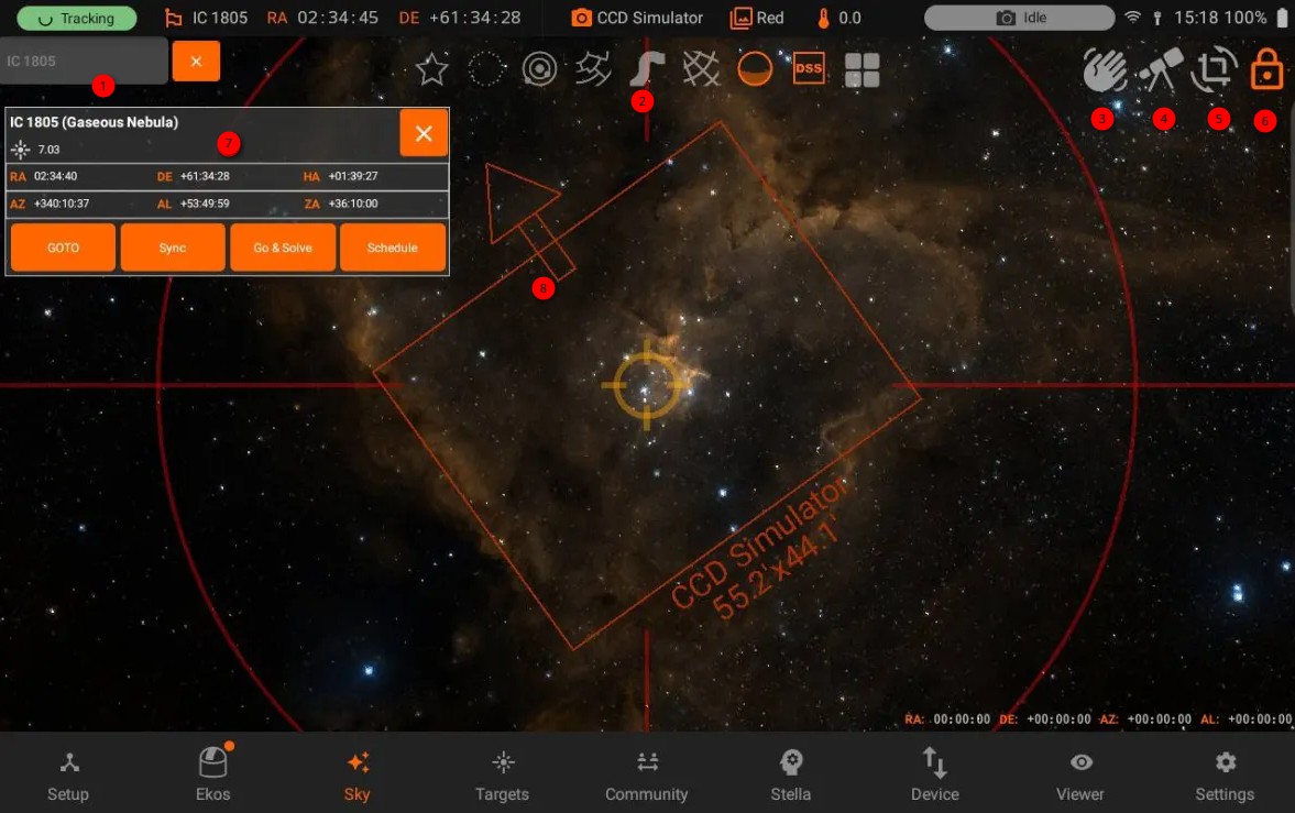
5.4.1. Search
Use the search function to locate objects from all available catalogs. Tap an object in the search results to center it on the map. The object information panel will display, showing its type and coordinates.
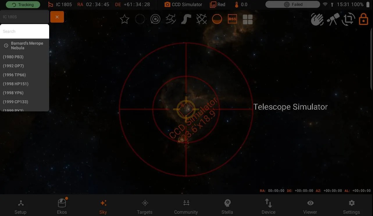
5.4.2. Objects Bar
Toggle the visibility of celestial objects and layers:
Stars
Deep Sky Objects
Solar System
Constellation Lines
Milky Way
Equatorial Grid
Horizon
Digital Sky Survey (DSS)
Mosaic Planner
5.4.3. Push To Assistant
The Push To Assistant is designed to help center objects on manual Alt-Az mounts using a camera aligned with the primary optical axis. For accurate operation, the camera must be precisely aligned with the eyepiece, as there is no offset compensation.
- Equipment Setup
To use this tool, create an equipment profile containing the following devices:
Telescope Simulator
Camera driver for your camera make.
When configuring your profile, select or create the telescope profile (Focal length and aperture). This refers to the smaller guide scope or finder scope used with the camera, not your primary telescope. Accurate telescope specifications are essential for proper plate-solving.
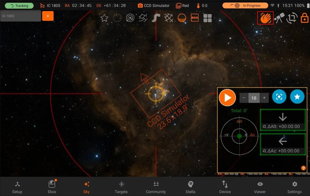
Centering Process
Target Selection: Select your desired object in the sky map, then sync the Telescope Simulator to it.
Initial Positioning: Manually move your mount as close as possible to the target object.
- Set Target Center: From the Push To Assistant window, choose your desired target center using one of these methods:
Star Icon: Select the currently selected object as the target center
Frame Icon: Select the sky map center as the target center
- Begin Centering: Press Start to initiate the process. StellarMate will:
Capture an image
Plate-solve the image
Display a correction vector showing how to adjust your mount to reach the target
Make Adjustments: Follow the correction vector to manually adjust your mount position. If you close to the target, make sure to make small gentle movements. The sky map will also show the Telescope Simulator position and the target position, so you can use the Sky Map as your guide during the centering process.
Wait for Next Cycle: After successful plate-solving, StellarMate will wait for the configurable delay period (10 seconds by default) before capturing the next image. This delay allows you to make mount adjustments without causing motion blur in subsequent captures.
Repeat: Continue this process until you achieve satisfactory centering results.
Plate-solving Tips
The Push To Assistant relies on successful plate-solving of captured images and uses the same settings specified in the Ekos Align module. It is generally recommended to first test plate-solving in the Ekos Align module to ensure it works correctly with your system, adjusting parameters like exposure time and gain appropriately for your equipment.
If plate-solving fails during Push To Assistant operation, simply wait for the next automatic capture attempt. If failures persist, consult the Alignment Troubleshooting guide for additional assistance.
5.4.4. Quick Mount Controls
Access mount controls to adjust speed, homing, parking, and tracking. Use the directional keys to manually move the mount.
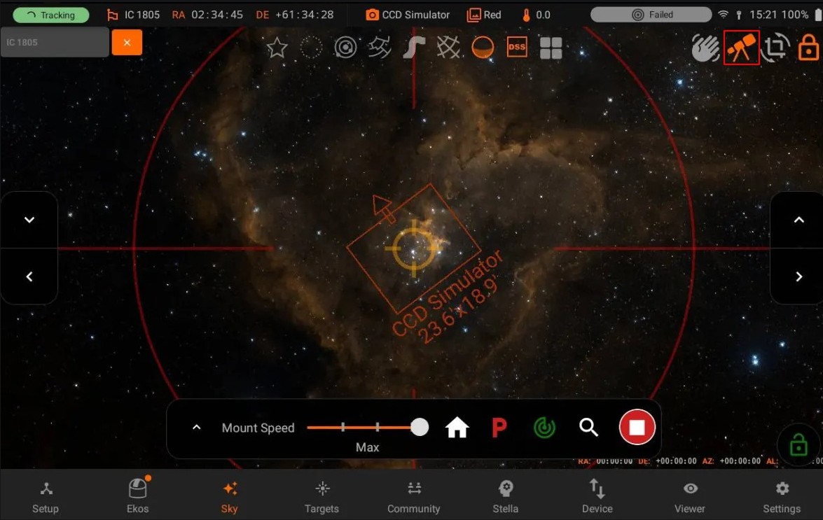
5.4.5. Lock Sky Map to Mount
When enabled, this option keeps the mount crosshair centered on the map even when the mount moves. This is useful for continuously monitoring the mount position.
5.4.6. Object Panel
Tap any object on the sky map to display the Object Panel. The panel shows the object’s magnitude (if available) and its horizontal and equatorial coordinates. You can perform GOTO, SYNC, or Go & Solve operations. The panel outer rim changes color to indicate the current operation status:
Magenta: GOTO in progress
Yellow: Plate solving in progress
Green: GOTO or plate solving complete
Red: An error occurred
5.4.7. FOV Indicator
At the center of the map, the Field of View (FOV) indicator shows the sky area visible to the camera sensor. The FOV size changes based on the selected camera and telescope. Below the FOV indicator, the camera name and width/height in arc-minutes are displayed. The up-arrow indicates the top side of the camera frame.
The Sky Map simulates the night sky using your device’s current time and location.
5.4.8. Mosaic Planner
Overview
The Mosaic Planner creates wide-field images by stitching multiple overlapping captures into a single large image. This allows you to capture targets larger than your telescope’s field of view without changing equipment.
Mosaic imaging involves two steps:
Capture multiple overlapping images of the target area
Process and stitch images together using external post-processing software
Enabling the Planner
The Mosaic Planner creates multiple Scheduler jobs based on a central target. To toggle the planner, press the grid button as shown below:
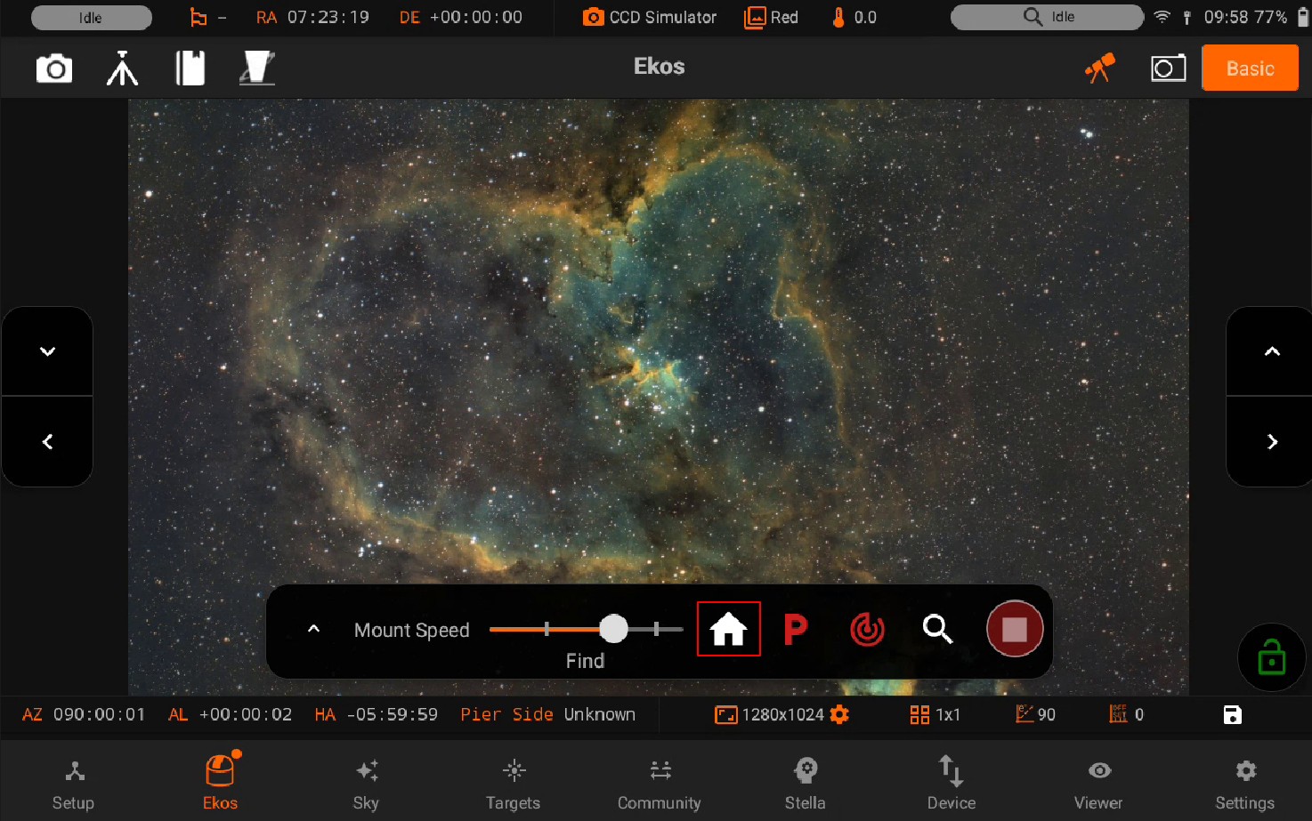
Configuring Mosaic Settings
Center the mosaic panel to the current sky map view or to a selected object using the recenter options.
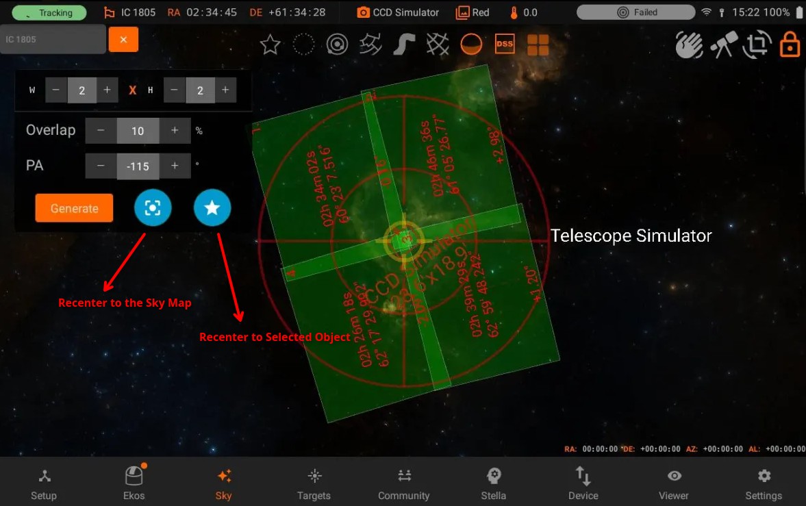
Configure the grid size and overlap percentage for the mosaic panels. Set the Position Angle to match the desired mosaic orientation in the sky. If the Position Angle differs from your camera’s usual orientation, you may need to rotate the camera manually or via a mechanized rotator when the scheduler jobs execute.
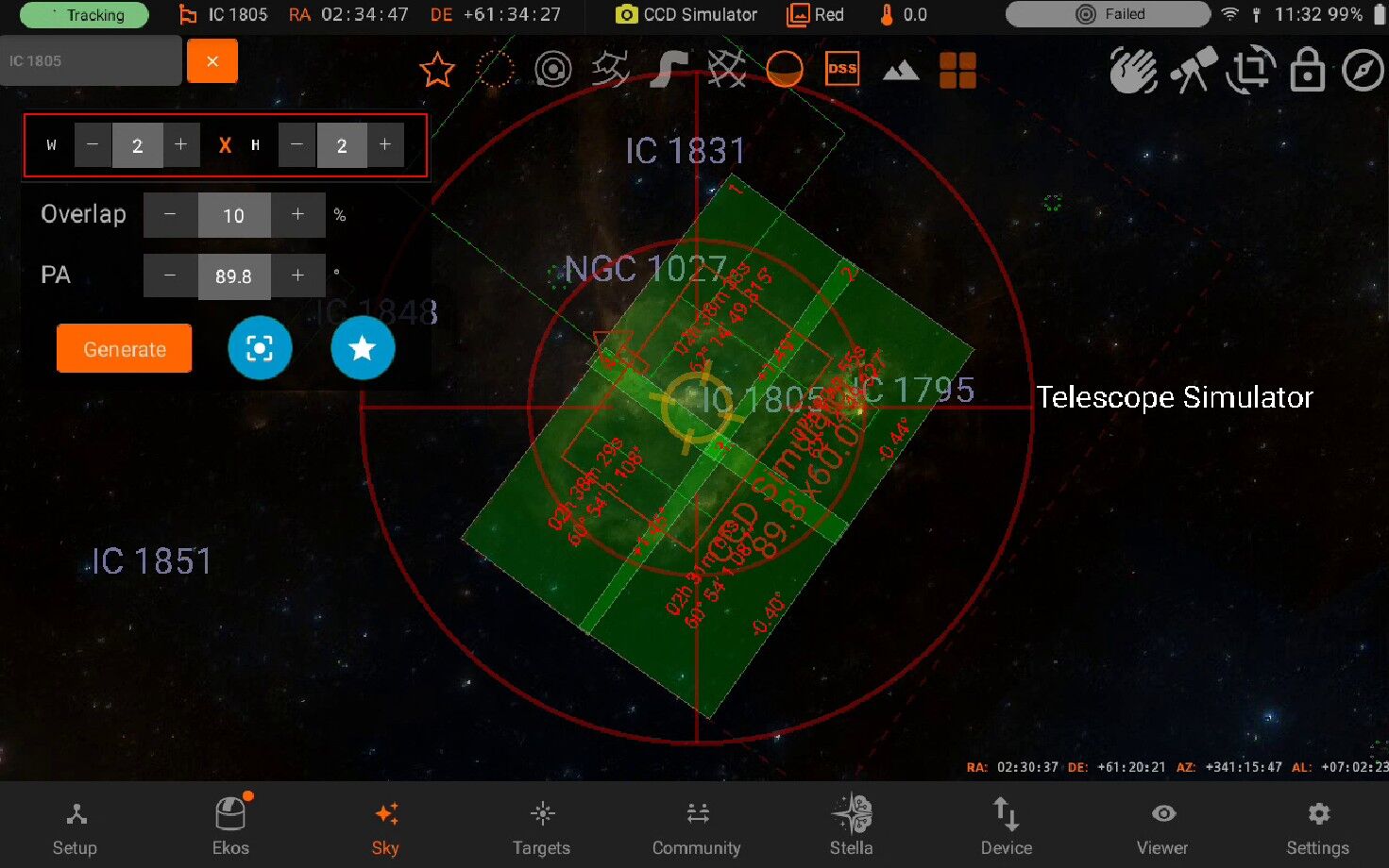
Creating Mosaic Jobs
Once configured, press Create Job.
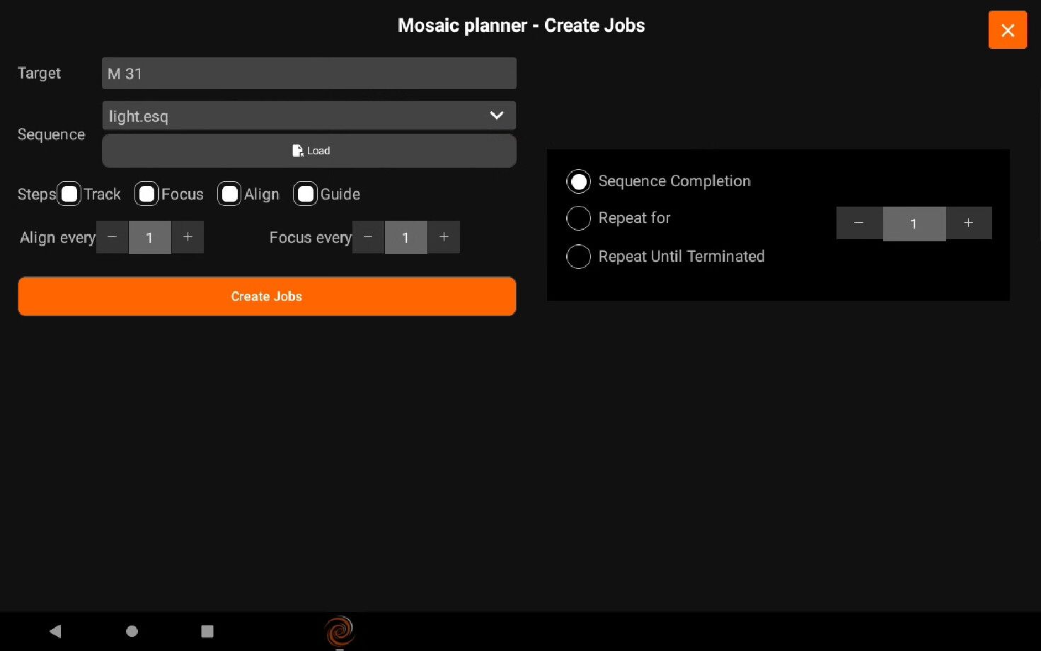
Select the sequence file for each tile. The Target field may be automatically filled but can be changed as needed. Select the steps each scheduler job should execute in sequence (Track -> Focus -> Align -> Guide -> Capture), and adjust the frequency of automatic alignment and focus routines during the mosaic operation. For example, if Align Every is set to 2 Scheduler Jobs, the first job will run astrometry alignment while the second job will skip it. When the third job executes, alignment is performed again.
To alternate between different mosaic tile jobs, enter a group name that all tile jobs will share and select a repeating completion condition.
Press Create Jobs to generate mosaic scheduler jobs and add them to the schedule queue. You can edit the jobs individually like normal Scheduler jobs.
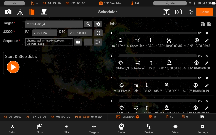
5.4.9. Artificial Horizon
Overview
The artificial horizon feature allows you to define a custom horizon line within the sky map. This can be useful to simulate the view from a specific location where natural obstructions like trees, buildings, or other landscape features block parts of the sky. By setting an artificial horizon, you can accurately represent the visible sky from your observing site and plan your observations accordingly. This helps in determining when celestial objects will rise above such obstructions, allowing for better scheduling of observations and imaging sessions.
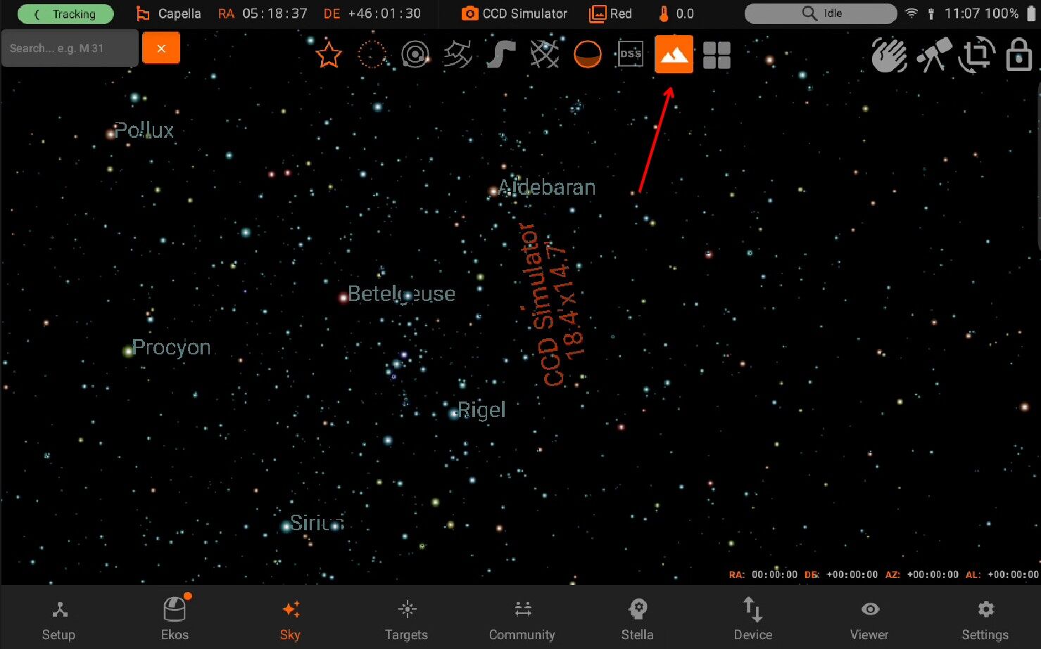
Once the Artificial Horizon is toggled, you can either select points manually on the map or import a horizon file.
Select Points To define horizon points manually, enable the Select Points option and tap the desired locations on the map.
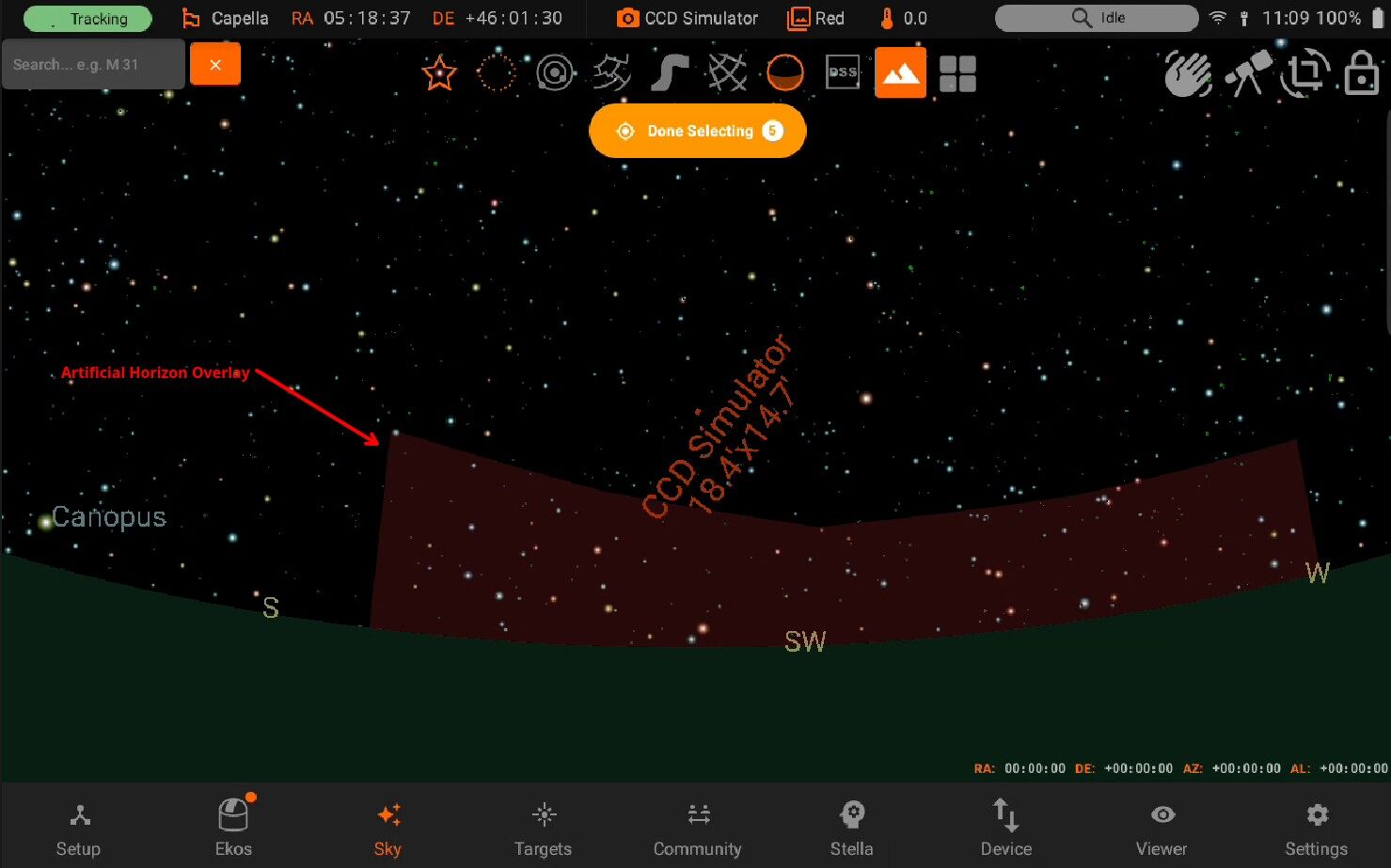
Once all points have been placed, press the Done Selecting button to activate the Artificial Horizon.
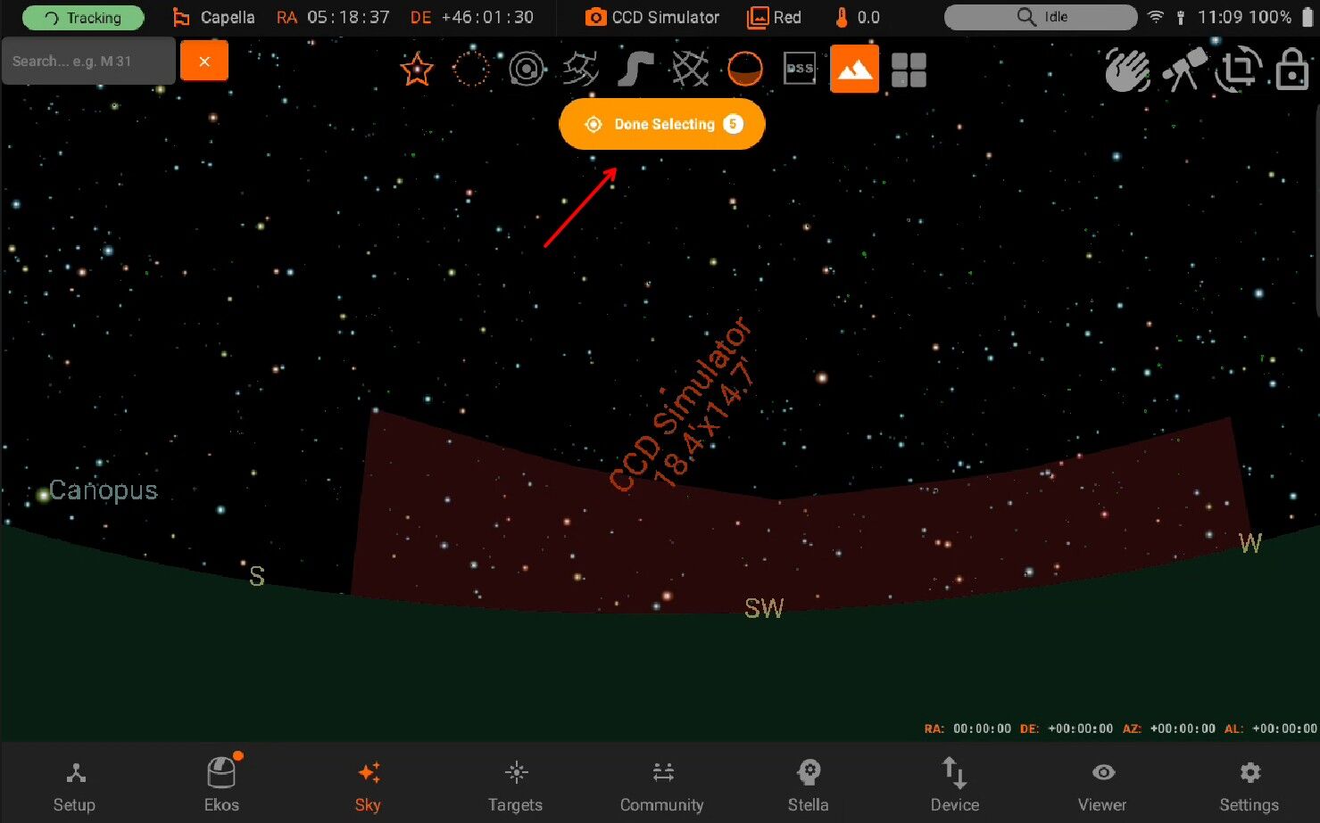
Import Horizon To activate the Artificial Horizon using a file, import a horizon file from your mobile device or tablet.
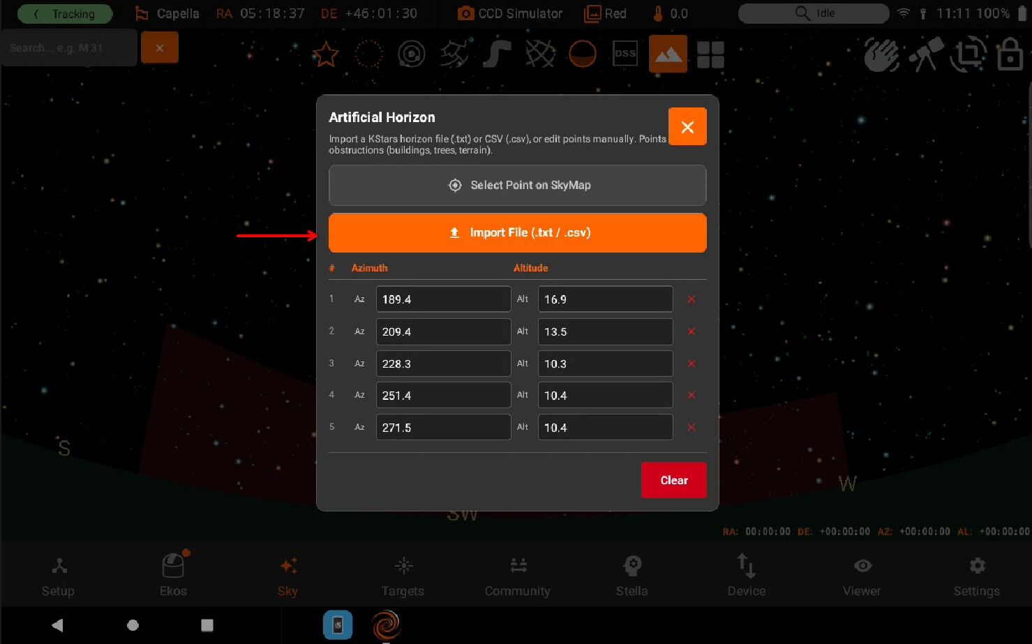
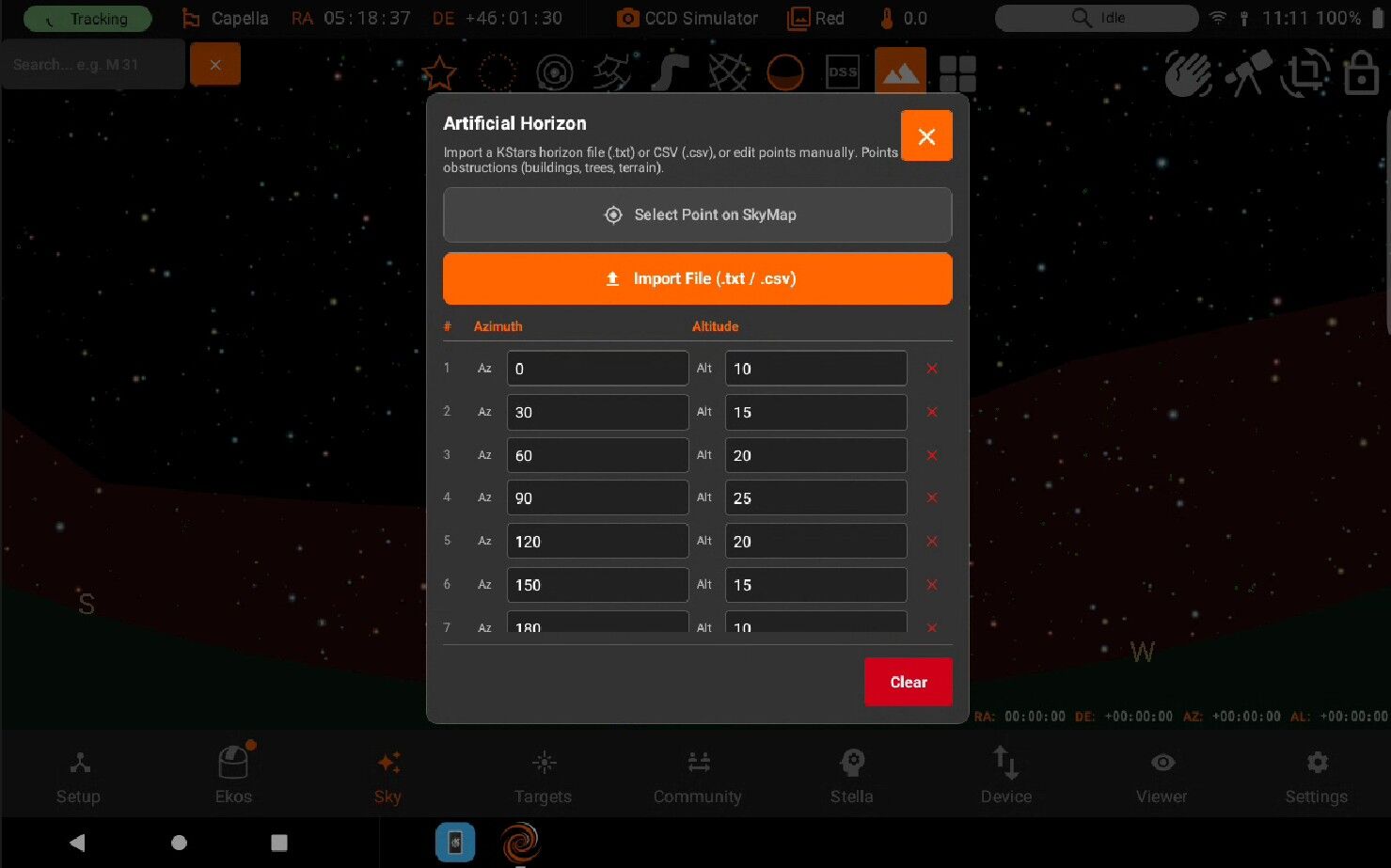
The supported file format is .txt. The file should be structured as follows:
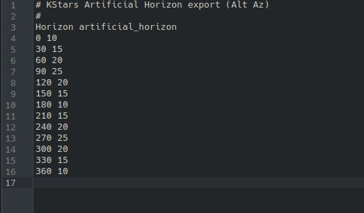
Once the file is imported successfully, the horizon overlay will appear on the Sky Map.
5.4.10. Framing Assistant
Overview
The framing assistant tool puts precise framing control at your fingertips. * Intuitive Interface: Easily adjust your target’s position and orientation within the frame using straightforward controls. * Clear Visual Feedback: See the exact area that will be captured with the field-of-view indicator, ensuring perfect framing every time. * Simple Adjustments: Make quick and precise adjustments to frame your subject exactly as you envision.
When you toggle Framing Assistant, the FOV Position angle and RA,DEC is synced to your current camera information. You can pan and rotate the desired FOV to Slew or Schedule.
You can see in the image below, the desired FOV is now pointing on other object.
Once your desired target is achieved, press Play Icon button to GoTo and Solve.
5.5. Targets
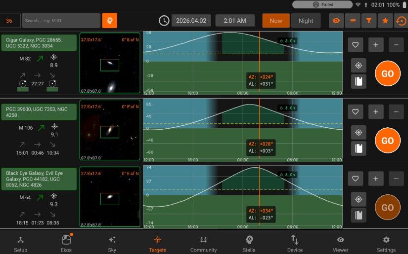
StellarMate Targets is the StellarMate Planning tool to streamline your observation session. Search from thousands of objects and filter them according to criteria important to every astrophotographer. Objects are sorted by brightest object first (if their magnitude is known). The number of objects listed is limited to the brightest 100 objects that satisfy the conditions set in the Filters section. To search for any arbitrary object, enter its name in the search bar and tap the Find icon. If the object is found, it should be added to the My Searches list. Add objects of interest to a quickly accessible Favorites list, or create and manage lists for your seasonal targets. Use the almanac info box to find Lunar, Solar, and Twilight times.
Tonight’s Best:
It displays the best sky objects available for observation on the current night.
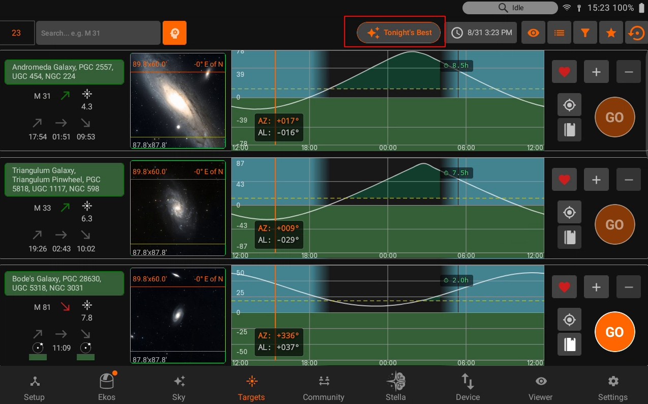
Pressing this button initiates loading of the object list, which may take a few seconds to complete.
Once the objects have loaded, they can be plate-solved, scheduled, or used with the Framing Assistant.
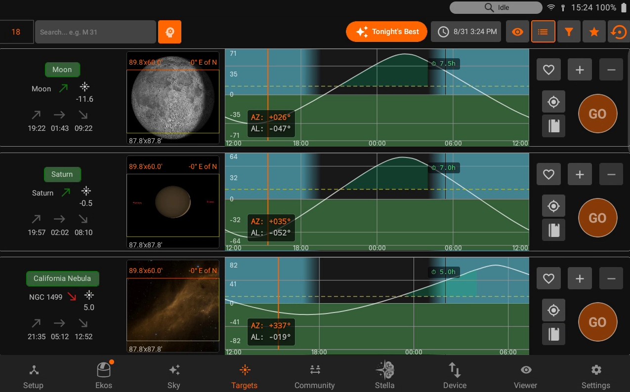
Date & Time:
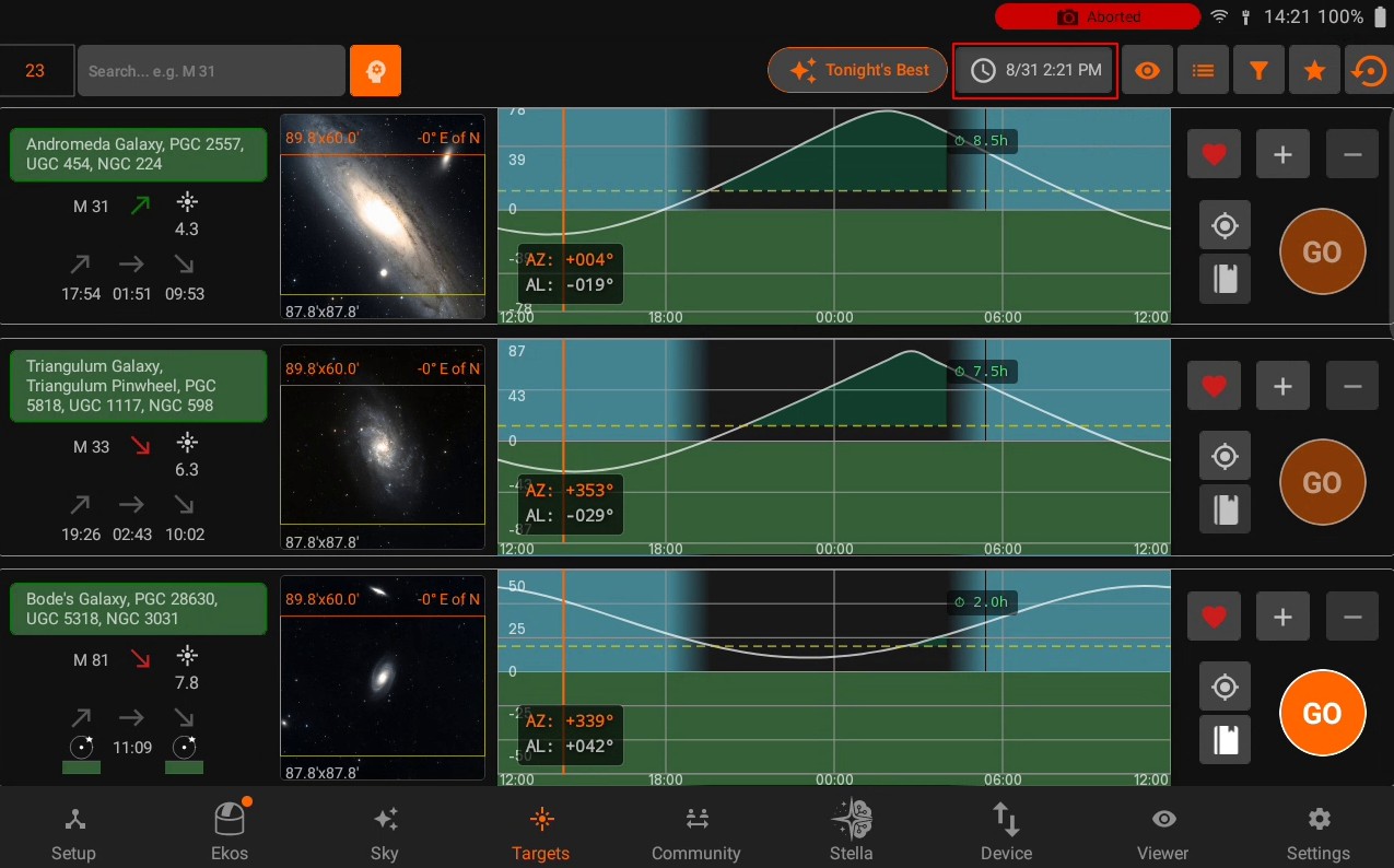
You can preview the targets available at a different date or time by changing the settings (This option is disabled if Ekos is running)
Sun/Moon Visibility
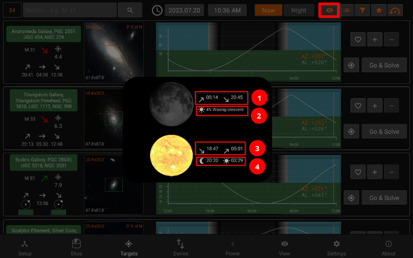
Moon rise/set times
Illumination percentage and lunar phase name
Sunset/Sunrise
Astronomical Twilight Dusk/Dawn
Filters
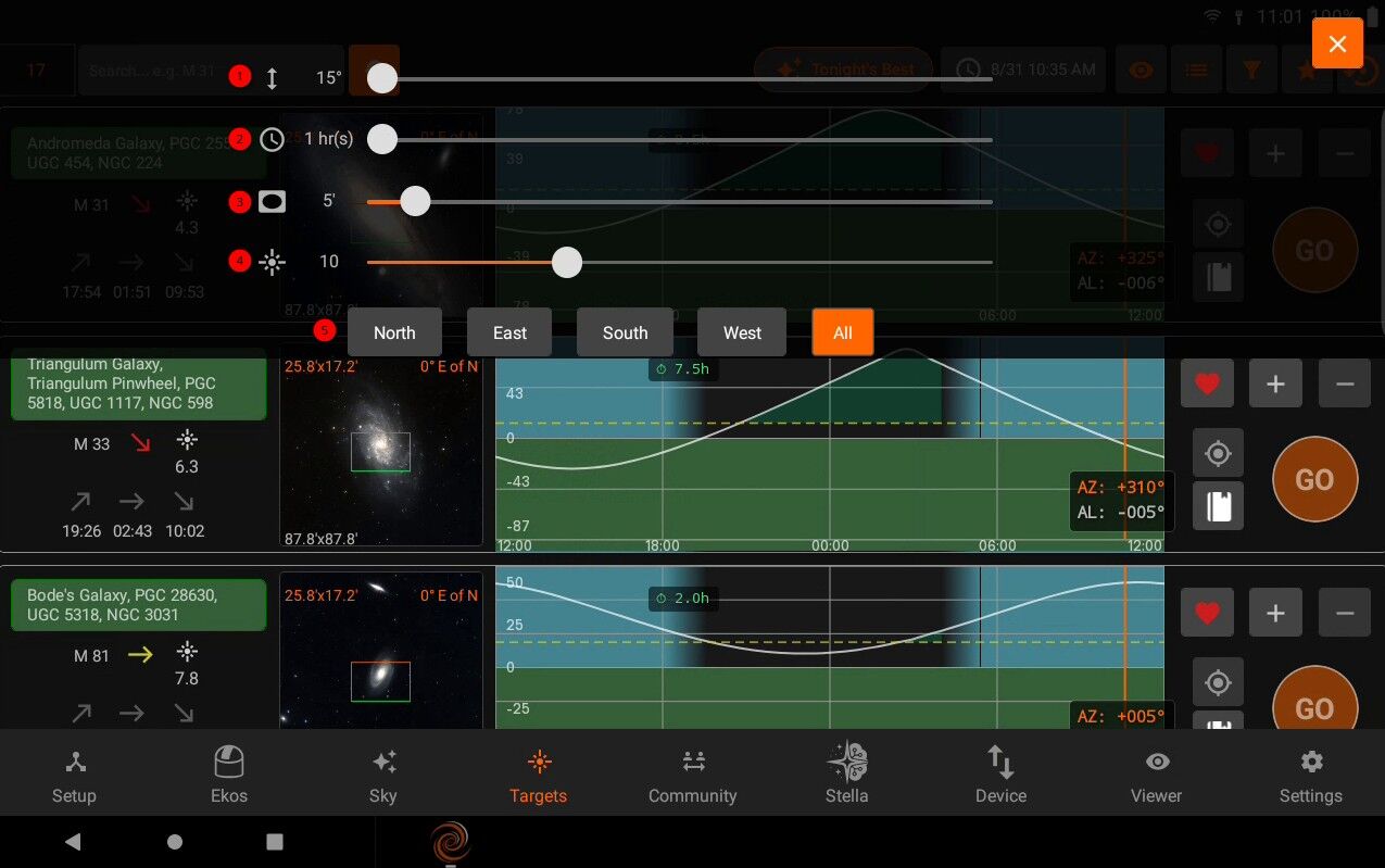
Minimum object alititude in degrees.
Minimum duration in hours where the object must meet the altitude condition above. For example, if altitude is 20 degrees, and duration is two hours, then only objects that remain above 20 degrees for at least two hours are going to be included in the search results.
Minimum Field of View (FOV) in arcminutes. This is only applicable to extended objects like nebulae and galaxies and not to point sources like stars.
Maximum Magnitude. Lower it to limit it to more bright objects.
Filter the objects by type.
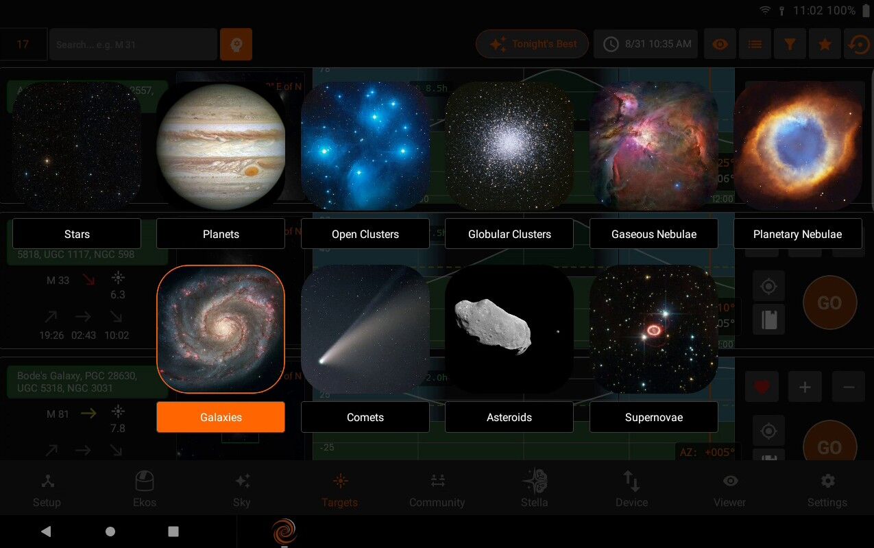
Search Results
Number of results
Filter by object name (only filters currently displayed results)
Extended Search: You can search for an object by name only without adjusting any filters. This would search for ALL objects of all types regardless of filters. If the object is found, it is then added to the My Searches list.
FOV Profile
You can overlay a Field-of-View (FOV) indicator on the top of the displayed image. This aids in target framing. By default, the FOV rectangle color is green with the top marked in orange. The top coincides with your camera/frame top. Using the overlay helps to determine exactly how l the target appears in a captured image. All units are in arcminutes. 1 arcminute is 1/60 of a degree. For reference, the Moon is 30 arcminutes or half a degree across the sky. When the equipment profile is running, the FOV for each connected camera is automatically generated. You can simply select it from the dropdown menu to activate it. Furthermore, you can add your own FOV indicators manually as illustrated below. In order to use the Framing Assistant, it is necessary to select an FOV profile first.
FOV profile dropdown
Add | Edit | Delete (FOV profile)
Exit list (returns to normal targets browsing)
Adding an FOV profile in opens up the following panel:
After setting the Focal Length, Camera width & height and pixel width & height, the FOV can be calculated by pressing the Calculate FOV button.
Lists
It contains Lists dropdown. Add, Edit the list name or Delete the selected list.
Target Info
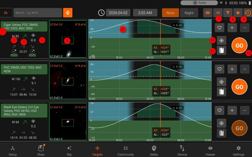
Object designations.
Object name.
- Object Phase:
Green: Object is rising
Yellow: Object is transiting the meridian
Red: Object is sitting
Magnitude
Object Image and FOV Overlay.
Altitude vs. Time Plot. The X-Axis designates time starting from 12 PM to 12 AM, with local Midnight (00:00) at the center of the image. The yellow vertical line indicates the current time. Next to the current time line are the object’s current Azimuth and Altitude values in degrees.
Add to Favorites.
Add to custom list.
Remove from current list.
Sync to the target.
Schedule the target
Go & Solve: Go to object and plate solve (required to use Framing Assistant).
When Ekos is offline, Targets will be used to schedule the coordinates information to Scheduler.
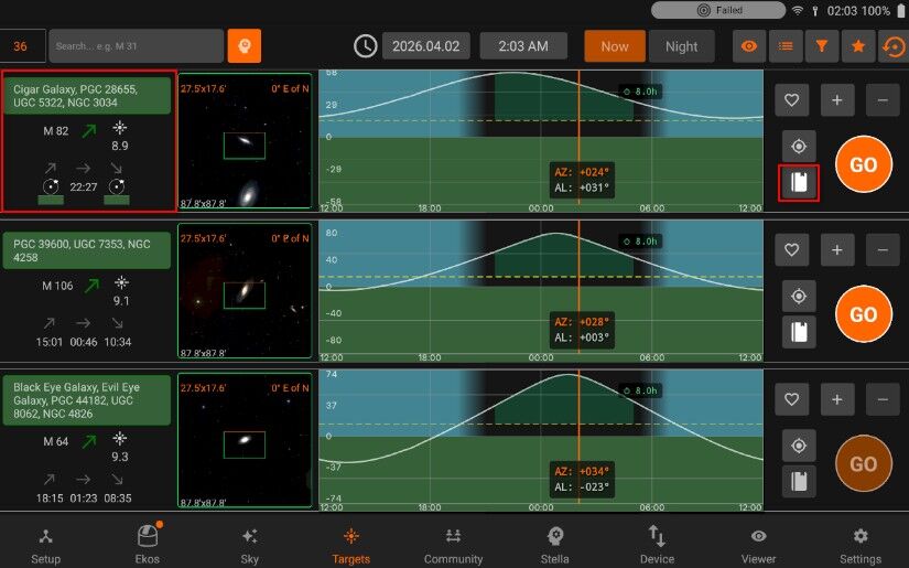
When Ekos is offline, you can also use framing assistant to Schedule the coordinates to Scheduler. The border of each target displays it’s status:
Idle: Grey
Plate-Solving: Yellow
Skewing to target: Purple
Plate-solving successful and target is centered: Green
Plate-solving unsuccessful or beyond acceptable accuracy threshold: Red
5.5.1. Framing Assistant
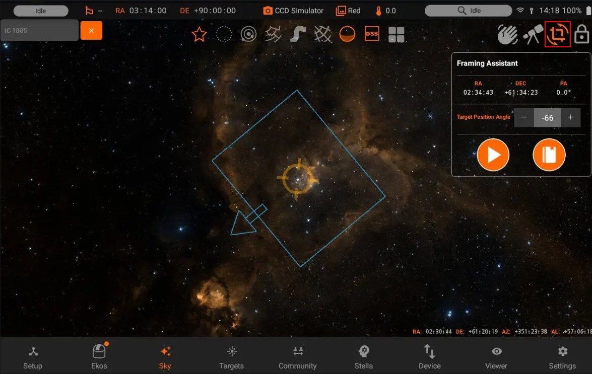
To open the framing assistant, make sure to have selected an FOV Profile and press Go & Solve.
StellarMate will command the mount to slew to the target location. This is indicated by a magenta border around the target. Once Slew is complete, the alignment process begins which is indicated by a yellow border. A red border indicated alignment error or alignment is not within threshold. Please wait until the solver iterates to center the target exactly in the center of the sensor. Once this is done, the border turns to Green. Now that the plate solving is complete, you may proceed to use the Framing Assistant tool that helps you in adjustment the orientation of the camera to match your desired orientation either manually or automatically if a rotator device is detected.
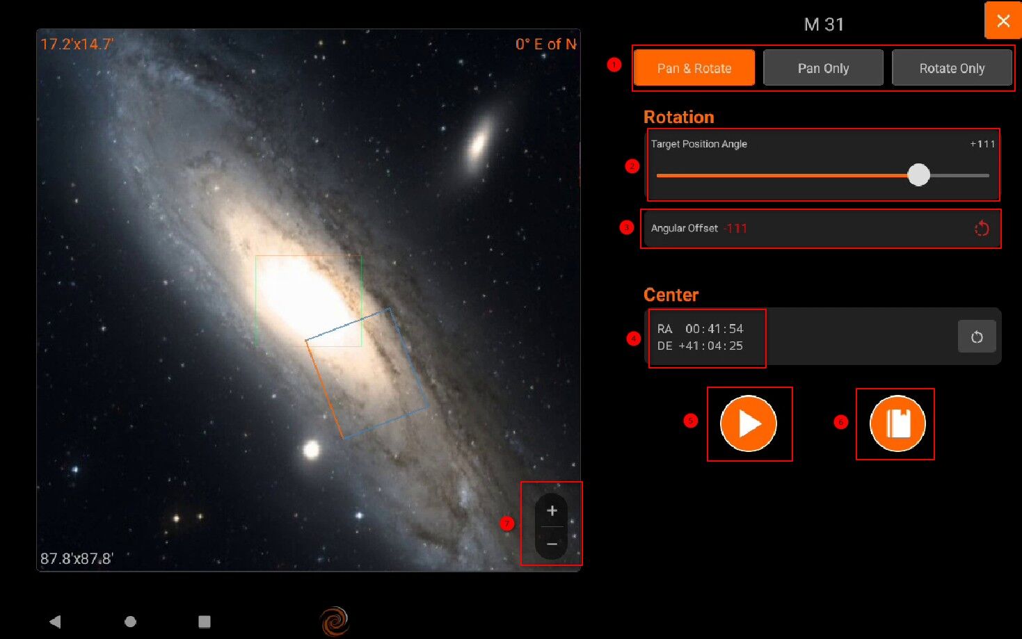
1. Framing Assistant The framing assistant tool puts precise framing control at your fingertips. * Intuitive Interface: Easily adjust your target’s position and orientation within the frame using straightforward controls. * Clear Visual Feedback: See the exact area that will be captured with the field-of-view indicator, ensuring perfect framing every time. * Simple Adjustments: Make quick and precise adjustments to frame your subject exactly as you envision.
To access the framing assistant, simply tap the target image. If the field-of-view (FOV) indicator isn’t visible, choose the desired FOV from the dropdown menu. For a more automated approach, tap Go & Solve to initiate a sequence of actions: the mount will slew to the target (marked by a magenta border), followed by plate solving to align the image (indicated by a yellow border). Pay attention to border colors during alignment: red signals an error or misalignment, requiring patience as the solver works to center the target. Once successful, a green border confirms perfect alignment, readying you for a perfectly framed capture. Once the status turns to green (1), press the image (2) to open the Framing Assistant. Adjust the rotation and/or position of the desired frame by using hand gestures to pan and rotate. Zoom in or out using the designated buttons to increase or decrease the field of view.
- The Framing Assistant provides three gesture modes to provide fine controls:
Pan & Rotate: Pan and Rotate the desired target frame freely.
Pan only: Only allow panning, no rotation permitted. This can help if you want to avoid accidentally rotating the target frame while panning.
Rotate only: Only allow rotation, no panning is permitted. This can help if you want to avoid accidentally panning the target frame while rotating.
If an automated rotator is connected, then all rotation commands are handled automatically by StellarMate. If no rotator is connected, you can manually adjust the camera. Set the desired target rotation first, then check the required Angular Offset value. Go to your camera and rotate it manually by hand using your best judgment. Tap play to measure the new orientation of the camera. Once plate solving is complete, the new camera orientation and angular offset are updated. Repeat this process as many times as necessary until you are satisfied with the result. Your goal is to bring the Angular Offset down to zero.
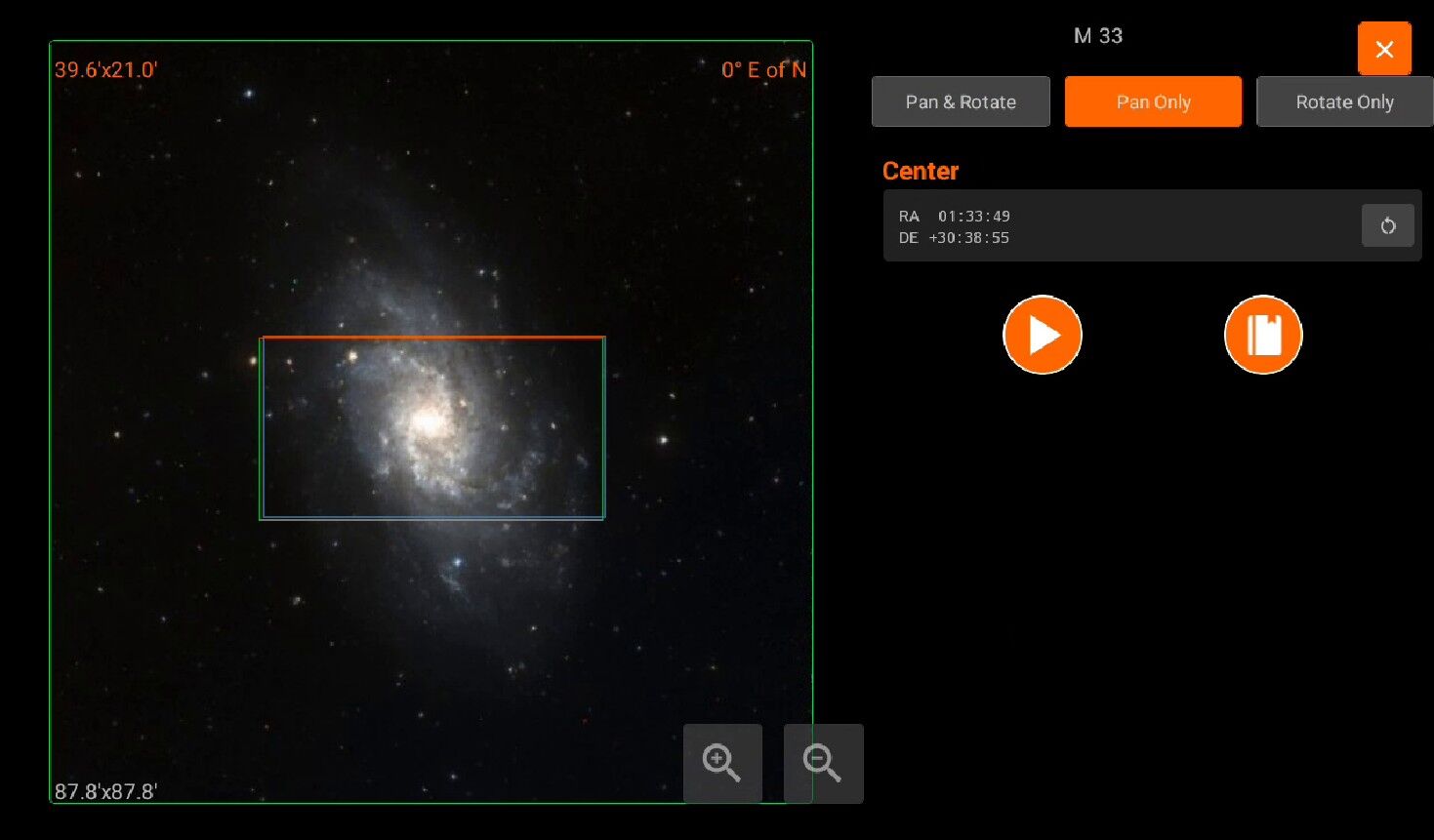
Adjust the rotation of the desired FOV orientation with either the slider or hand gestures. The target FOV rectangle color is blue with orange designating the top. The green rectangle with orange on top is your camera’s current FOV & orientation in the sky.
Rotation offset in degrees between the current (Green) FOV and the target (Blue) FOV. When manually adjusting the camera, rotate it clockwise or counterclockwise as per the indicated icon.
J2000 Center Right Ascension & Declication coordinates.
Once all the necessary adjustments are made, tap GOTO & Rotate to start the framing process. If a rotation offset is required, Ekos will issue a GOTO command followed by a rotation command if applicable.
Add the target to the Scheduler module. This commands Ekos to plate solve and adjust the captured image frame to match the desired position angle either automatically (if a rotator device is connected) or manually.
Zoom in/out to get the desired HIPs Object image.
If Ekos is offline, you can Schedule your target coordinates by using framing assistant in Scheduler module.
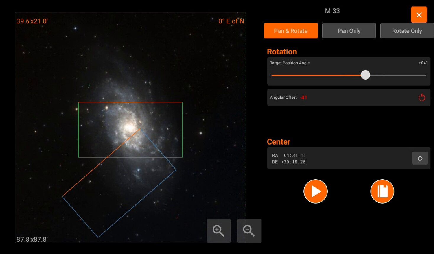
5.6. Community
You must agree on StellarMate App’s community terms and conditions, so you can access the community tab. If the agreement is found to be violated, your account will be removed.
Share your images with fellow astrophotographers, browse equipment from numerous manufacturers, manage your observatory, and customize your EkosLive social profile in the Community section of StellarMate App.
Share your post-processed astronomical images with rich equipment and acquisition metadata, thanks to seamless EkosLive integration.
Create equipment profiles for your observatory that include all your physical hardware, then map them to Ekos equipment profiles so INDI drivers are automatically matched to your gear.
For advanced features such as Observatory Rentals, Live Video feeds, and much more, visit EkosLive Online.
The Community section consists of four sections:
Profile: View your profile.
Feed: See posts from users.
Equipment: View Equipment manufacturers and models
Observatory: See your observatories
Tap on the comment icon to open or close the comments section for any post.
To view the user’s equipment, toggle the Equipment Profile option. This will display the observatory equipment used in the post.
You can tap the Equipment icon to see the equipment details directly.
Toggle the Acquisition Info option to view the filters and settings used to capture the image. This helps you understand the capture parameters used by the user.
For more detailed information, tap the Acquisition Info section to see the full capture settings.
If you come across a post that is not related to astronomy or astrophotography, you can report it. Tap the Report button to flag the post for review.
5.6.1. Leaderboards
Overview
Community Leaderboards allows you to compete with other StellarMate users. It displays a ranked list of the top 50 users. XP is calculated based on the following criteria:
Number of posts uploaded to EkosLive
Number of captured objects
Total number of achievements completed
Tap a user’s badge to access their profile, where all uploaded posts are displayed.
From the profile, you can also view the user’s completed achievements and captured objects.
The main leaderboards screen also provides access to your own profile statistics.
From your profile, you can review all captured objects.
You can also track all completed and pending achievements.
5.6.2. Profile
You can view any user’s profile by pressing on their username of profile badge.
You can also view any of the user’s post in detail. For example:
5.6.3. Equipment
View all Equipment manufacturers, models that are available with StellarMate Device. You can also search devices, manufacturers and models
View Manufacturers
Add Equipment Manufacturer
Once you submit a manufacturer, StellarMate support will view it and if all good, it will be published to the relevent Equipment device.
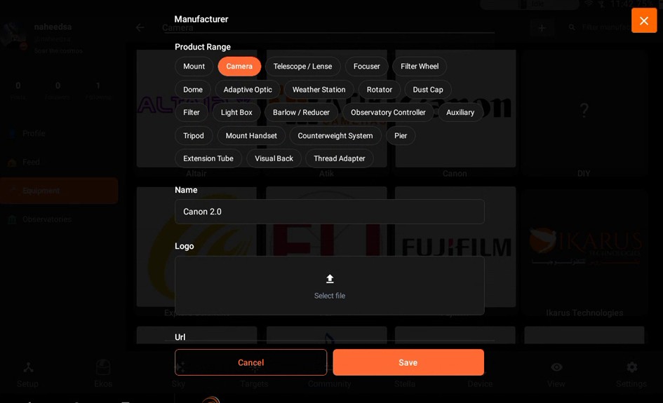
View All Models
Add Equipment Model
Once all details are filled, you can submit it and after StellarMate support approves your request. It will get published.
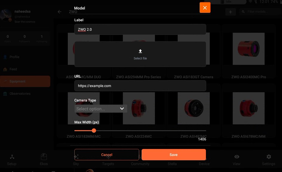
View Model
5.6.4. Observatories
You can view here your Observatories. That can be managed. You can also rent your Observatory but it is currently available in Ekoslive Online. Please check Public Observatories <https://ekoslive.com/community/profile/observatories/>_ for more info.
By default, Observatory is created and can also create your own Observatory if needed.
You can press on the desired observatory to view it’s details. Scroll down to see full weather details.
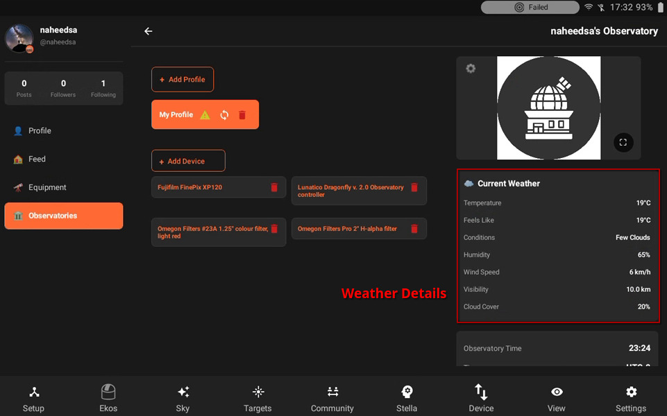
Press on Observatory Settings to modify it.
You can add multiple images to the Observatory, Update location and you can also share your Observatory’s location and make it public.
Select your Observatory’s location from the map and set it.
Your Observatory must be synced to your equipment profile.
If you see an warning sign next to the profile name, that means your profile is not synced.
You can sync profile by pressing on this icon button.
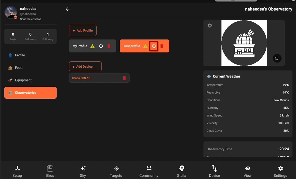
You can select or create an Equipment profile.
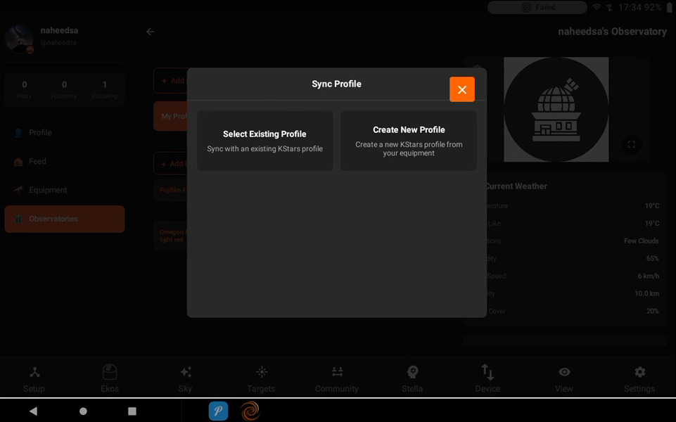
If you create an profile, it will be create with the name of same profile.
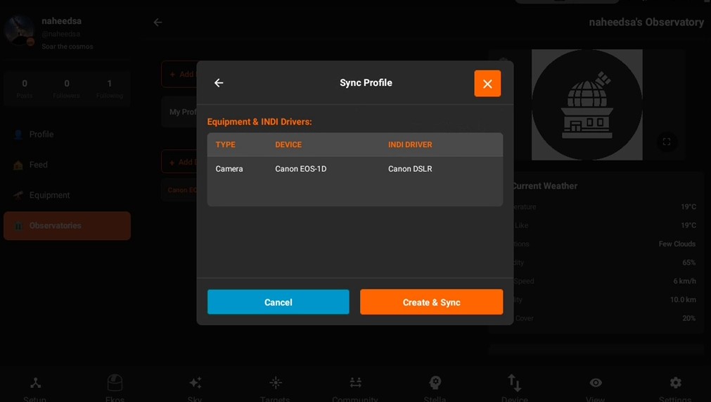
5.7. Stella
Stella is a smart assistant for EkosLive & StellarMate App. It can query information from online or offline data sources including your equipment, weather, and environmental conditions. You can communicate with Stella using natural language via text or voice. To use Stella, the StellarMate App must be connected to the internet. You can command Ekos to perform complex functions including creating image sequences and scheduling targets. To speak to Stella, press the microphone button and talk. After you complete your request, you can press the microphone button again to transcribe your voice to text. This gives you the chance to edit the text before sending it to Stella. Alternatively, you can directly press the enter button to send the voice request directly to Stella. It is also integrated with the Targets and View tabs. In targets, use Stella to find targets of interest. For example, you can ask Stella to find all globular clusters above 50 degrees that are brighter than 5th magnitude. For EkosLive Pro subscribers, Stella can also search your cloud images using any number of criteria (e.g. Find all images for Heart Nebula captured in HA filter in the last 2 months). Since all images are uploaded with rich metadata, you can use many fields to narrow your search. To create sequences, start by saying Capture followed by your request. For example:
Capture 20 frames each 5 seconds long
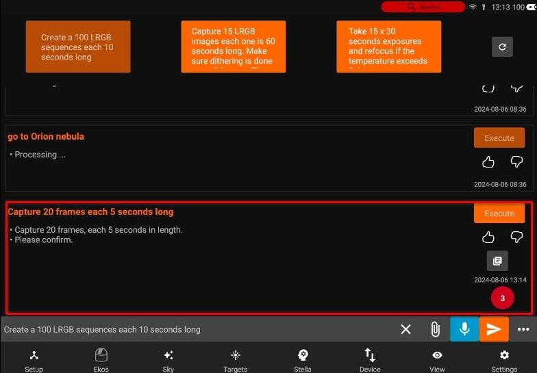
If Ekos profile is running, Stella will generate an XML file that can be dispatched to Ekos. You can inspect and view this file before Executing it. To execute a request, tap Execute or simply type or say Execute. Once executed, you can go to the Ekos tab to check the progress.
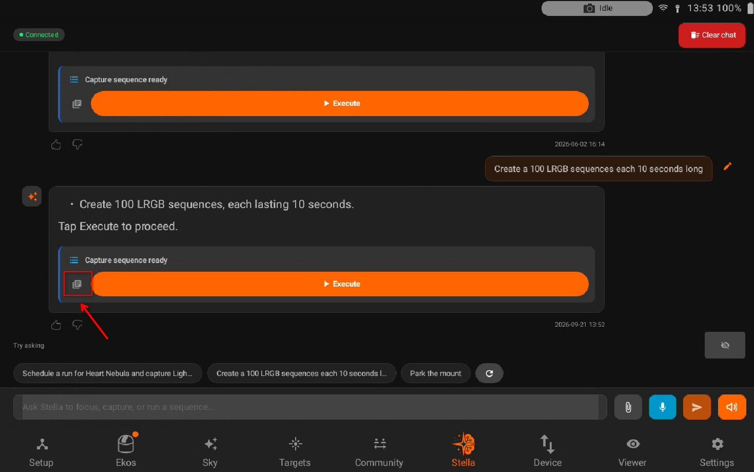
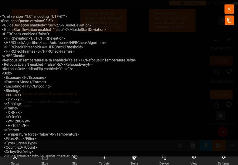
After Pressing execute button, you can see sequence jobs are in progress.
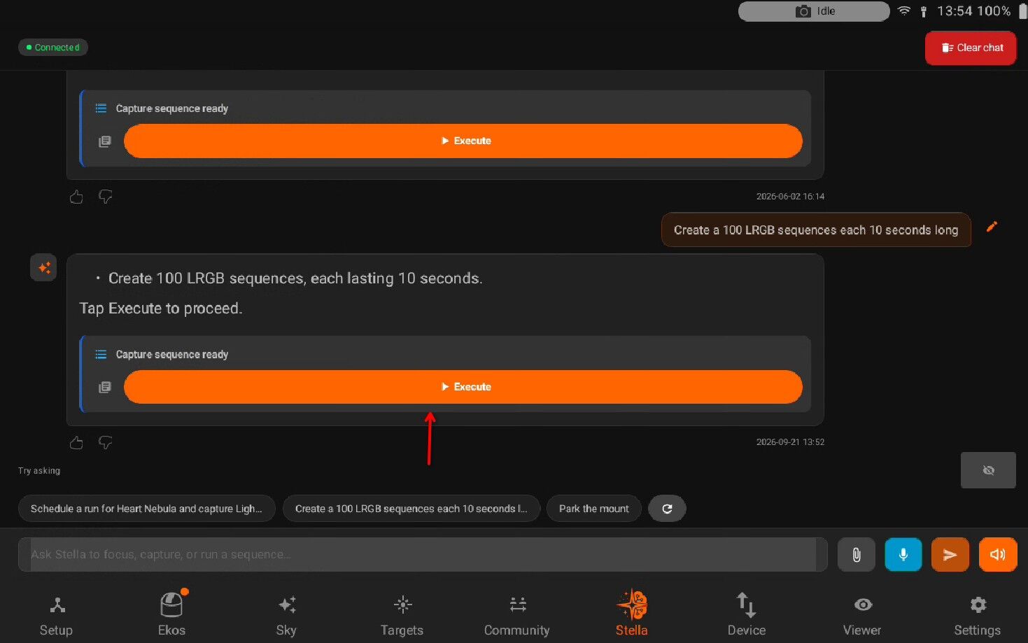
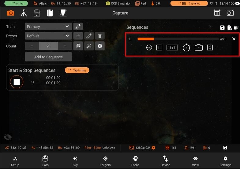
Scheduling targets requires the target name and the sequence details. All requests must start with Schedule. Schedule M42 and capture 10 frames each 60 seconds long in RGB filters. If the request is successful, Stella will generate the sequence and scheduler XML files. Stella uses the default settings in your equipment profile and only alters the parameters explicitly set by you in the request. Each Stella request includes one or more parameters. Depending on the request type, you can specify any of the parameters below:
Capturing a sequence
Guide RMS
Guide Start RMS
HFR deviation
HFR Algorithm
HFR threshold
HFR check frames
Refocus delta T
Refocus time
Meridian Flip refocusing
Exposure time
Color format
Encoding
Binning
Filter
Type
Count
Delay
Dither setting
Directory
Upload Mode
Flat Duration.
Scheduling a target
Target
Startup Condition
Minimum altitude
Weather
Twilight
Artificial Horizon
Step
Searching targets
Minimum altitude
Maximum magnitude
Type of object
Direction
Minimum duration
Minimum FOV
Maximum FOV
Julian Date
Filtering images
Filter
Frame
Minimum and maximum air mass
Binning
Date
Minimum and maximum exposure
Object name
5.8. Device
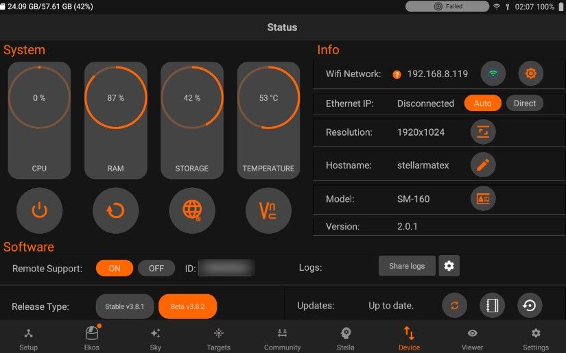
The Device page manages the health, settings, and updates for your StellarMate. It is divided into the following sections:
System
Info
WiFi Network
Ethernet
Resolution
Hostname
Software
Firmware Updates
Remote Support
Logs
Sharing logs
5.8.1. System
- System shows the Utilization of SM device. It includes:
CPU
RAM
Storage
Temperature
It also has main controls i.e
Access Web Manager. It can also be accessed from the browser i.e http://localhost:8624
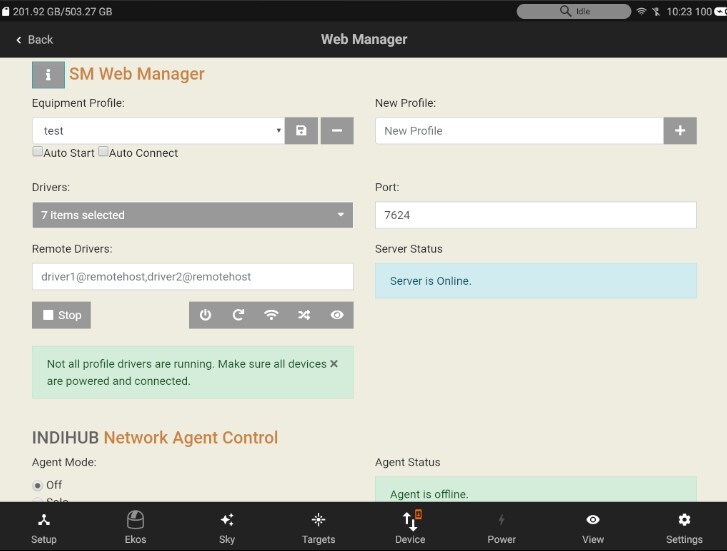
Access of VNC. Can be accessed from the browser i.e http://localhost:6080
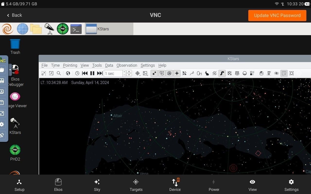
You can also update your VNC password by pressinng on the top right “Update VNC Password”
5.8.2. Network
Your equipment profile may contain one or more serial port and/or network-enabled devices. Before establishing connection to such devices for the first time, StellarMate Port Selector tool helps you to assign the appropriate ports and addresses for each. Serial devices may include mounts, focuser, and filter wheels using USB-to-Serial adapters. You need to know the baud rate for the device as by default it is set to 9600.
Note
PORT SELECTOR IS NOT APPLICABLE TO PURE USB DEVICES SUCH AS CAMERAS.
For networked devices over Ethernet or WiFi, you need to supply the device host name or IP address and the device port. This information is usually supplied by your device manufacturer. It is important to ensure that all networked devices are within the same network as StellarMate. For example, if StellarMate is operating in hotspot mode (IP 10.250.250.1) then your network-enabled device must be connected to the same hotspot network and have an IP address in this range (e.g. 10.250.250.5). On the other hand, when StellarMate is operating in infrastructure mode (i.e. it is connected to an external WiFi network like Home WiFi), then the other network-enabled devices must be connected to the same network in order for all devices to talk to each other.
The Port Selector dialog can be accessed as any time by click on the Port Selector button. When creating an equipment profile for the first time, it is automatically opened so you can configure the ports before establishing connection to your devices either individually or via clicking Connect All buton.
You can specify the ports for serial and network devices using the Port Selector.
The serial ports can be selected from the drop-down. The addresses are unique to each connected device (similar to COM1, COM2..etc on Windows OS) but the automatically generated port names usually do not tell you which device they are connected to. When you have multiple serial devices, it can be tricky to find out which is which. StellarMate automatically tries to connect to the serial devices and attempts handshake with each device, but this might lead to multiple drivers trying to talk at the same time to multiple devices which might lead to traffic collision.
Therefore, it is better to select the correct ports from the beginning. This is only required once in the initial setup. One method to know a device’s serial port is simply by connecting one device at a time via USB, and then check the serial port that is displayed in the drop-down. Make note of this port name and then connect the next device and check again, the new serial port in the drop-down should belong to the 2nd device. Now you know for certain the ports for the connected devices.
Once the ports and network settings are selected, press Connect All to establish connection.
Connection Status
Green: device is connected.
Yellow: connecting to device.
Red: connecting to device failed.
Connection Mode
Serial: For mounts, filter wheels, and focusers that are connected via a Serial-to-USB adapter. To connect to serial devices, you need to select the port and baud rate. StellarMate provides the detected system ports in a drop-down menu to select from, but you can also enter your own port manually.
Network: For any network-enabled device (e.g. Mounts over WiFi like SkyWatcher AZ-Gti).To connect to networked devices, ensure they are connected to the same network where StellarMate is connected to. You need to enter the host-name or preferably the IP address of the device in addition to the connection port and connection type (TCP or UDP).
Baud Rate: Set the devices baud rate
Connect All: Connects to all the devices and closes the Port Selector
When connecting a serial device, you can specify the port by selecting from the drop-down or typing it in the text field
For network devices, you have to specify the host-name or IP of the device and the port. Also you can choose the network type (TCP/UDP). Info
5.8.2.1. WiFi Network
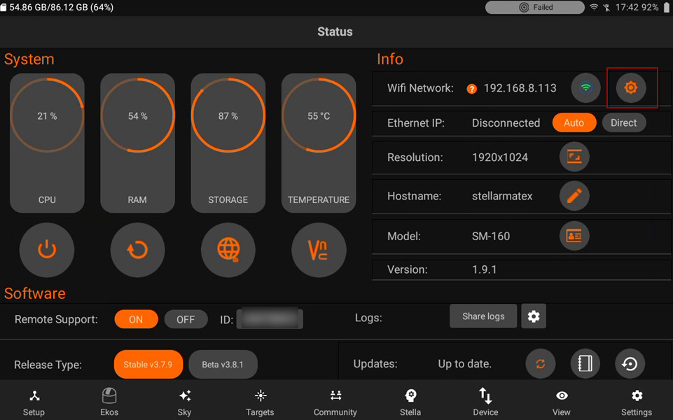
Toggle WiFi network by pressing on the button as shown in the image above.
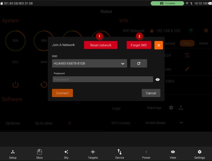
Reset Network: Network configuration gets reset. Make sure to reboot after resetting.
Forget WiFi: WiFi network information is removed and StellarMate reverts to HotSpot mode (IP Address 10.250.250.10). If the Unit is connected to your LAN via Ethernet, you can still access it via its LAN IP address like before.
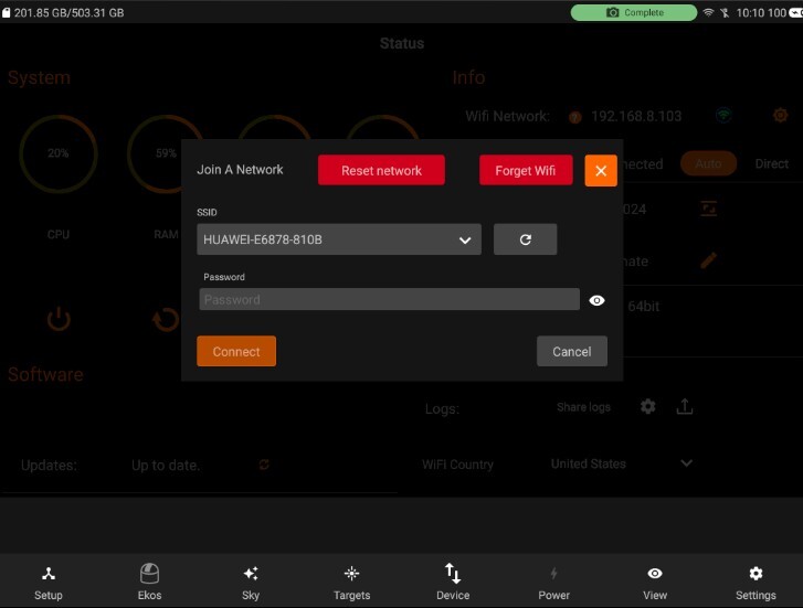
Connect to Home WiFi: Select a WiFi network as detected by StellarMate and then supply the password if it is protected. Press connect, After a successful connection, please wait up to 2 minutes before using any of the unit functions again.
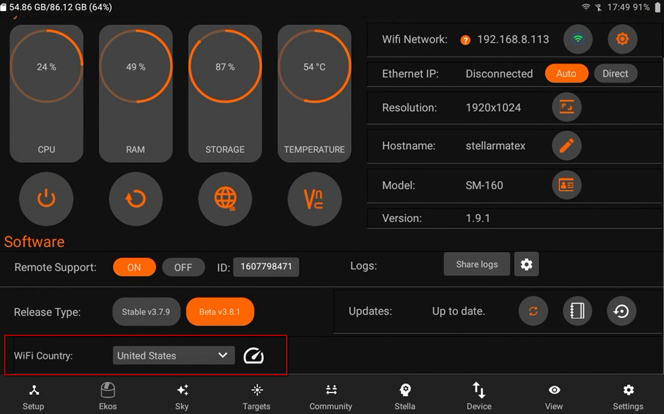
You can set your current WiFi country. It modifies your WPA network file. It is essential for compliance with local regulations regarding wireless communication frequencies, power levels and other parameters.
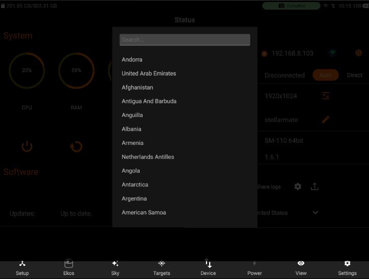
5.8.2.2. Changing Hotspot WiFi Band
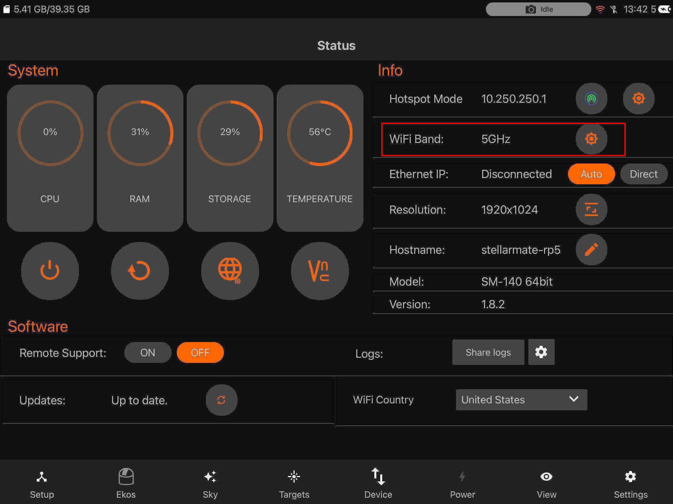
5.8.2.3. Ethernet IP
There are two methods for Ethernet connections:
- Direct Ethernet Connection Between StellarMate and your PC/Laptop: This can be useful in the field if you want a fast response time, at the expense of more cables. Ethernet is always faster and more reliable than WiFi connections (at the moment at least). When using Direct Connection, the HotSpot is activated

- LAN Ethernet Connection: Connect Ethernet to Router/Switch. Your router shall assign an IP address for StellarMate automatically, or you can configure the router to assign StellarMate a permenant IP address.
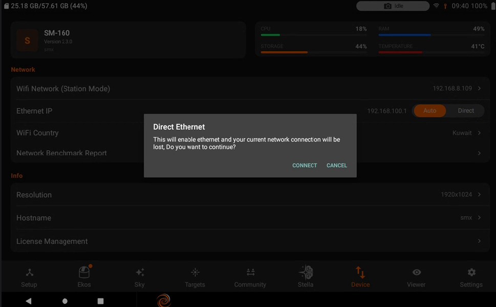
5.8.3. Info
Device Info includes:
Resolution
Host-name
License Management
5.8.3.1. Resolution
Change Resolution: Select available monitor display and change its resolution.
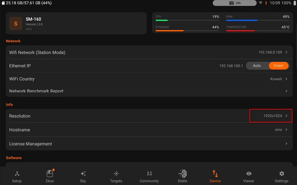
Change external monitor: If you are using model SMA-120 and it’s connected with an external monitor. You can select that one.
5.8.3.2. Hostname
Change Name : You can change device name (and its hostname) to another name without any spaces. For example, if you rename it to myobservatory, the host name shall be changed to http://myobservatory.local.
Apply entering desired hostname, press “Apply” and reboot your SM unit to get settings applied all over.
5.8.3.3. License Management
Each purchase, whether a StellarMate OS software license or a StellarMate X, Pro, or Pro X hardware unit, generates its own serial number. Hardware units ship with their serial pre-assigned and printed as a QR code on the device, which you scan during registration in the app.
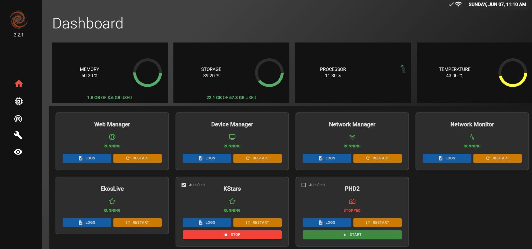
After signing in and connecting to a StellarMate Controller, the app automatically binds one of your serials to that controller. No action is needed the first time you connect a new device.
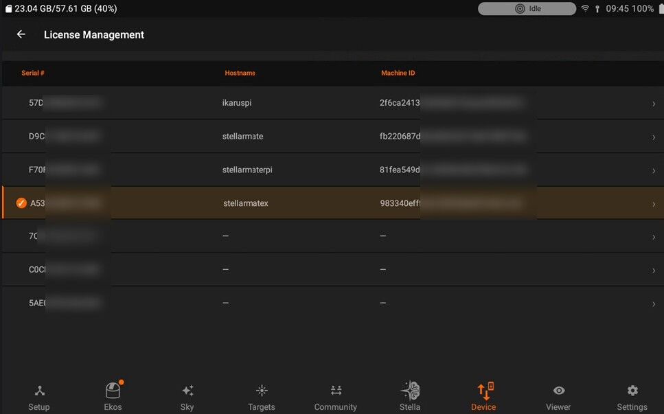
You can view all serials on your account, along with the controller each one is bound to, under Device then License Management (this option appears once your account has more than one license).
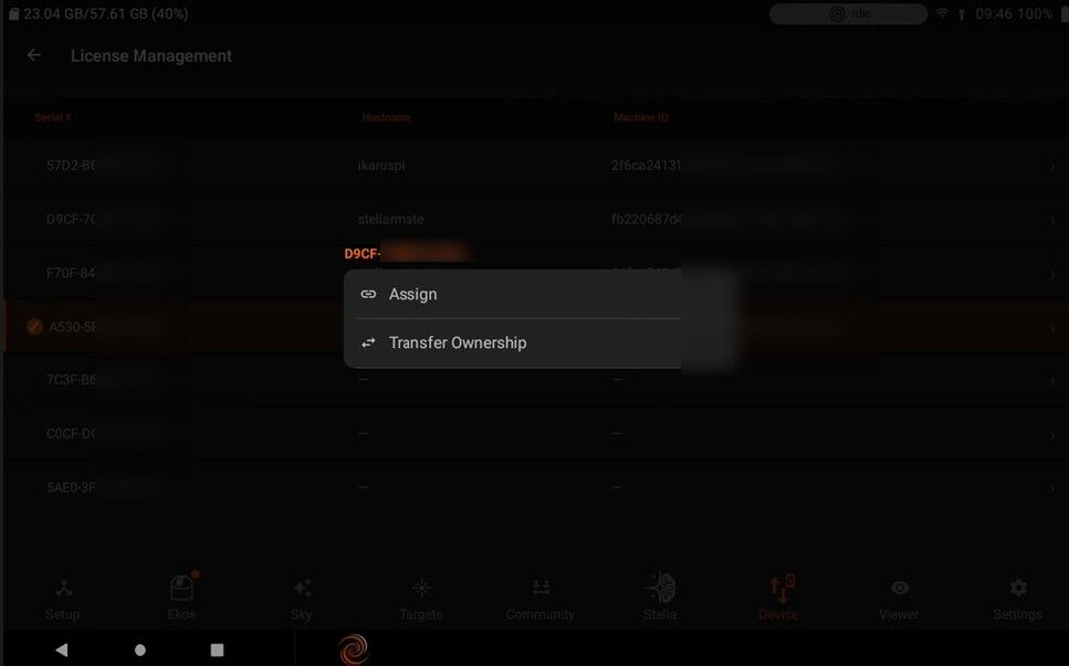
Once a serial is bound, it is tied to that specific controller. If you need to move a serial to a different controller, for example after replacing a device or if binding did not happen automatically, open License Management, select the serial, and tap Assign to bind it to the currently connected controller.
If a StellarMate Controller is factory reset, the app will usually detect this automatically and re-establish the binding the next time you connect, without any input from you. If instead you see a message that all your serials are already assigned to other devices, open License Management and manually assign one to the reset controller.
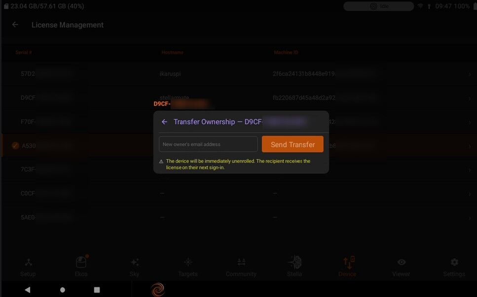
Releasing a serial: Only hardware serials (StellarMate X, Pro, and Pro X) can be released, for example if you sell or gift the unit. StellarMate OS software serials are non-transferable and cannot be released. In License Management, select the hardware serial and tap Release, then confirm. Once released, the serial becomes unclaimed, and the new owner can scan the QR code on the unit during their own registration process to claim and bind it to their account.
License Management can alternatively be accessed through EkosLive:
Open EkosLive and sign in to your account.
Navigate to Account Settings, where the License Management section is located.
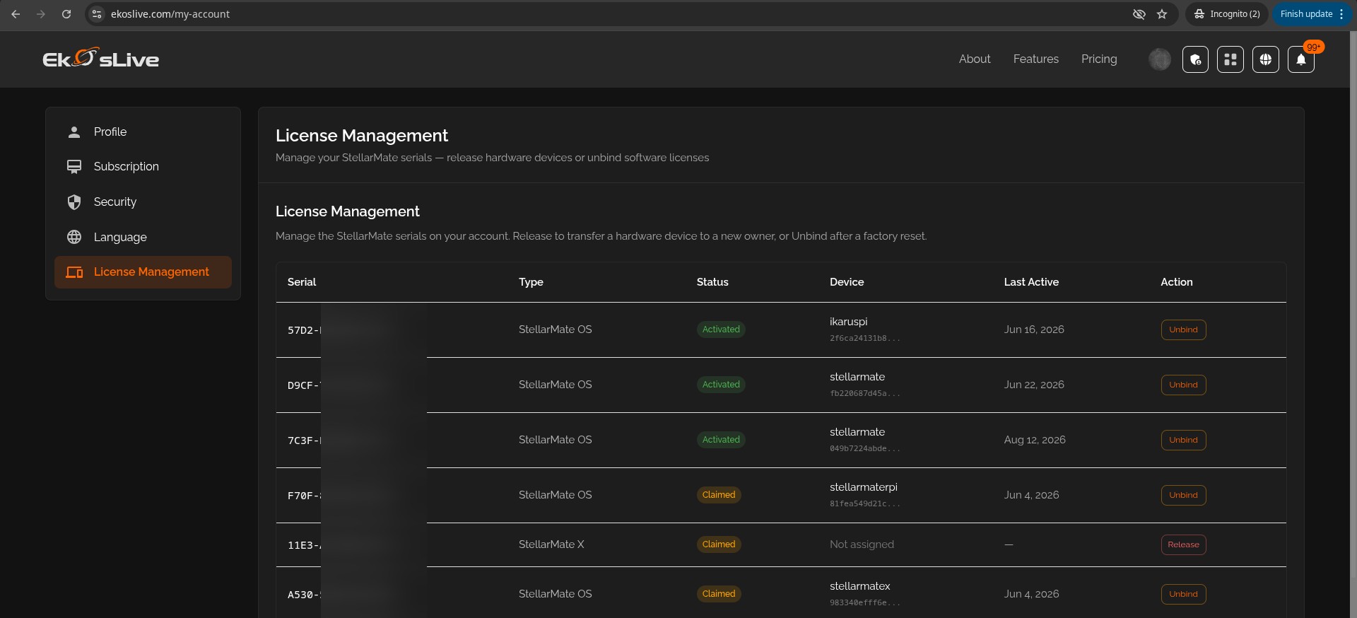
All serials associated with SM OS and SM Hardware are listed here.
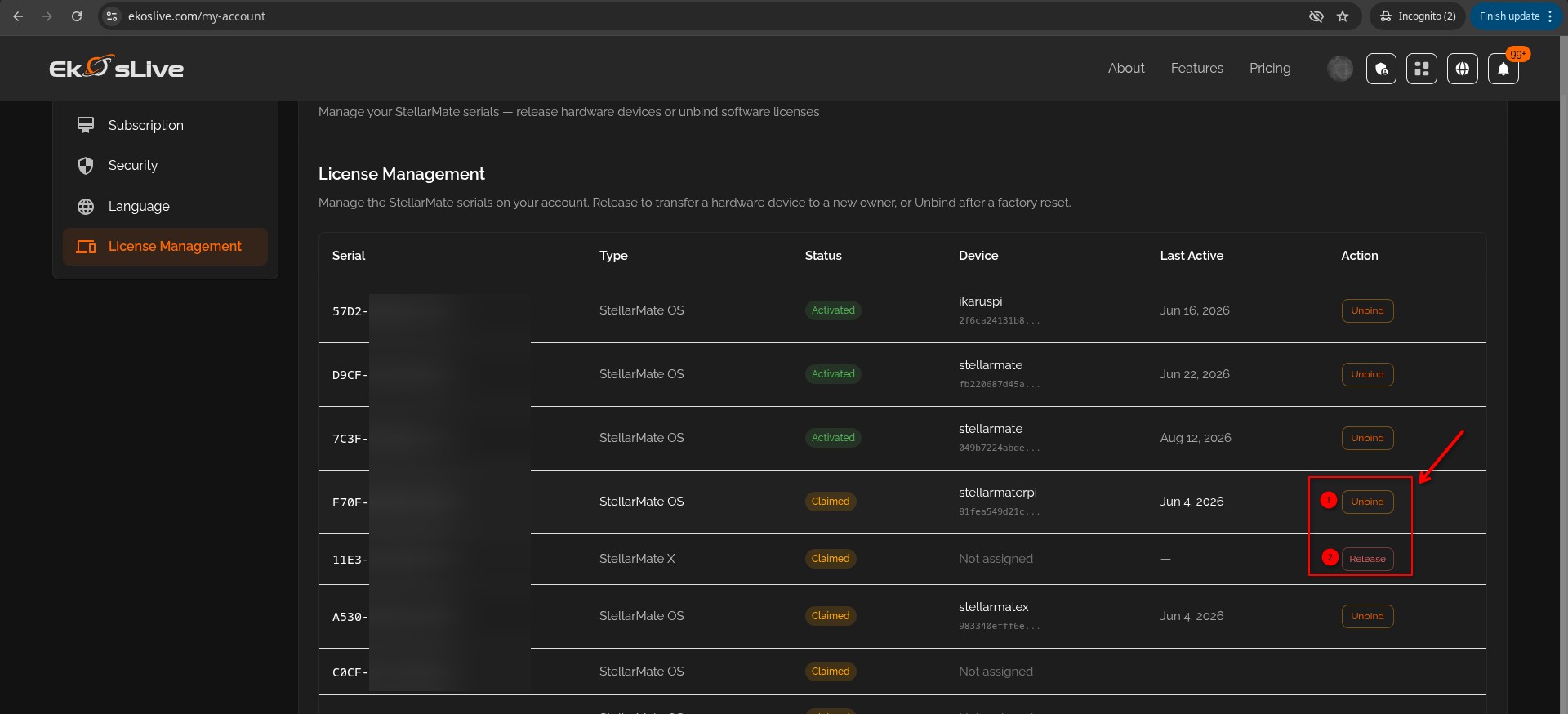
Any serial may be unbound if it is no longer needed.
For SM Hardware, selecting Release allows the license to be prepared for sale.
5.8.4. Software
- SoftwareYou can handle the SM OS updates and to give access to SM support using remote support ID.
Firmware Updates
Remote Support
5.8.4.1. Firmware Updates
When there is an update available for StellarMate, an icon will show up on Device tab.
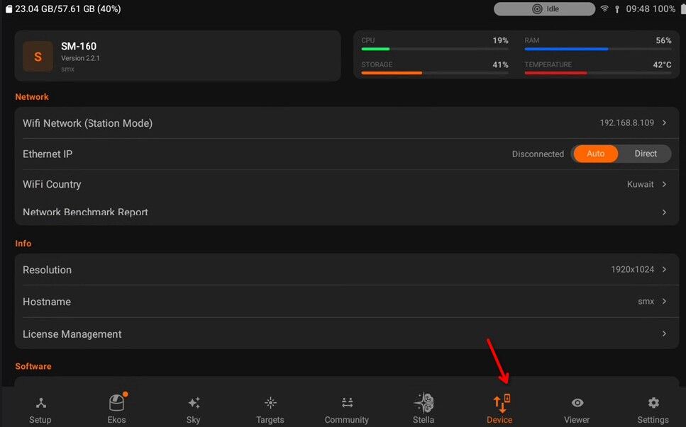
To update StellarMate, simply click the download button and wait for the the process to complete.
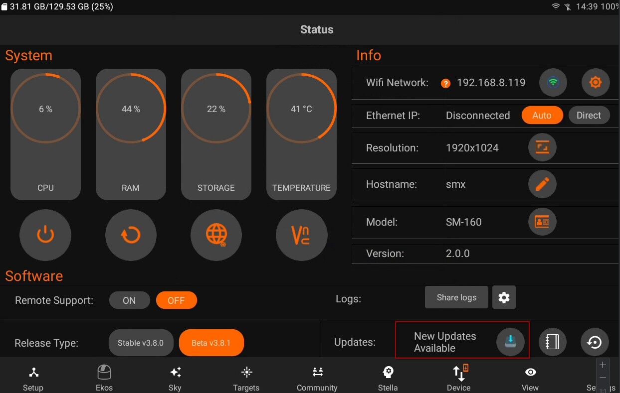
Delta Updates
Updates are delivered as complete, tested packages and applied all at once to maintain system consistency. Delta updates download only the changes, reducing bandwidth usage. To roll back an update, open StellarMate App or StellarMate Tools and select a previous version. This ensures reliable recovery, especially for remote setups.
If delta updates are available, you will see a popup with a detailed view.
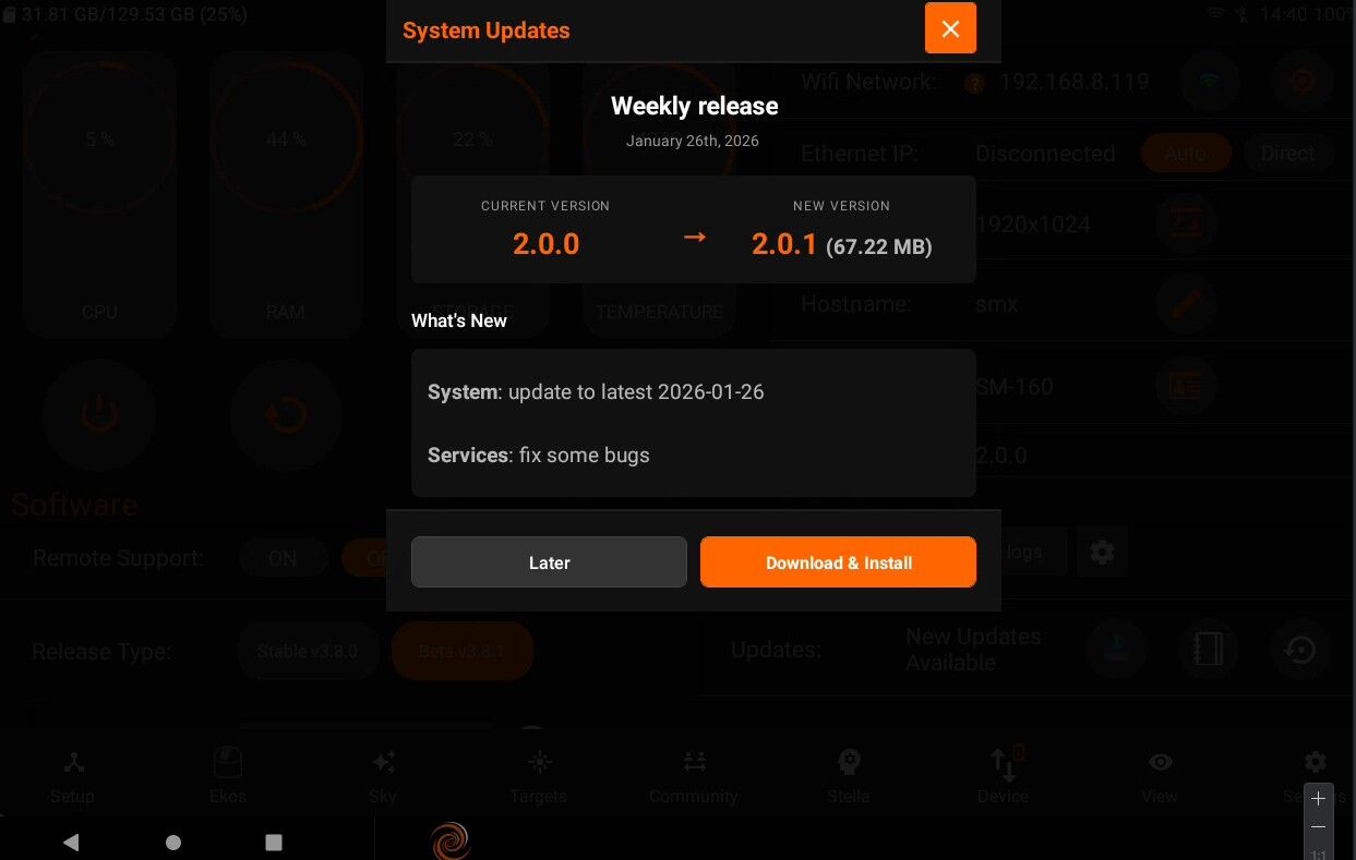
Once you start downloading, you can also see the download progress.
If there are no delta updates, then the system will only apply hot-fixes.
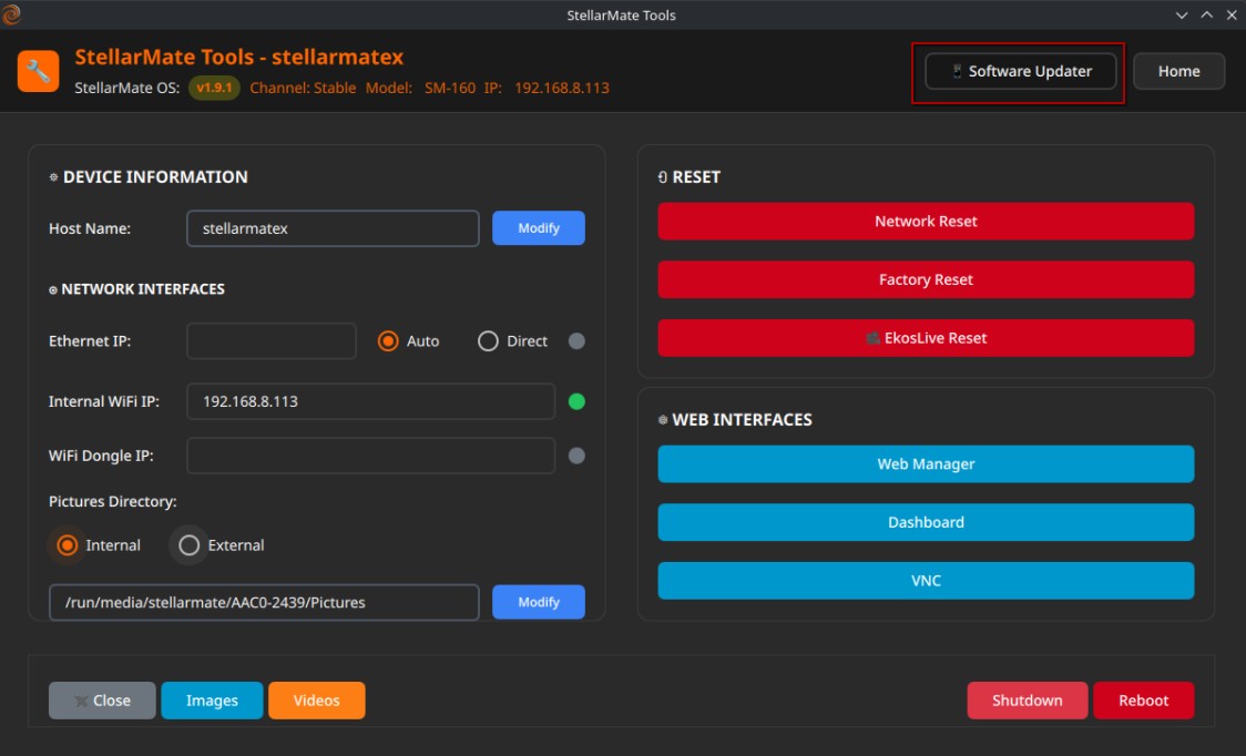
Once the update is complete, you will be prompted to restart Stellarmate for the updates to take effect.
Rollback
The system automatically creates snapshots before updates and configuration changes. To restore a previous state, open StellarMate App or StellarMate Tools, select a snapshot from the available list, and confirm to restore the system. Use snapshots to safely test configurations and roll back changes when needed.
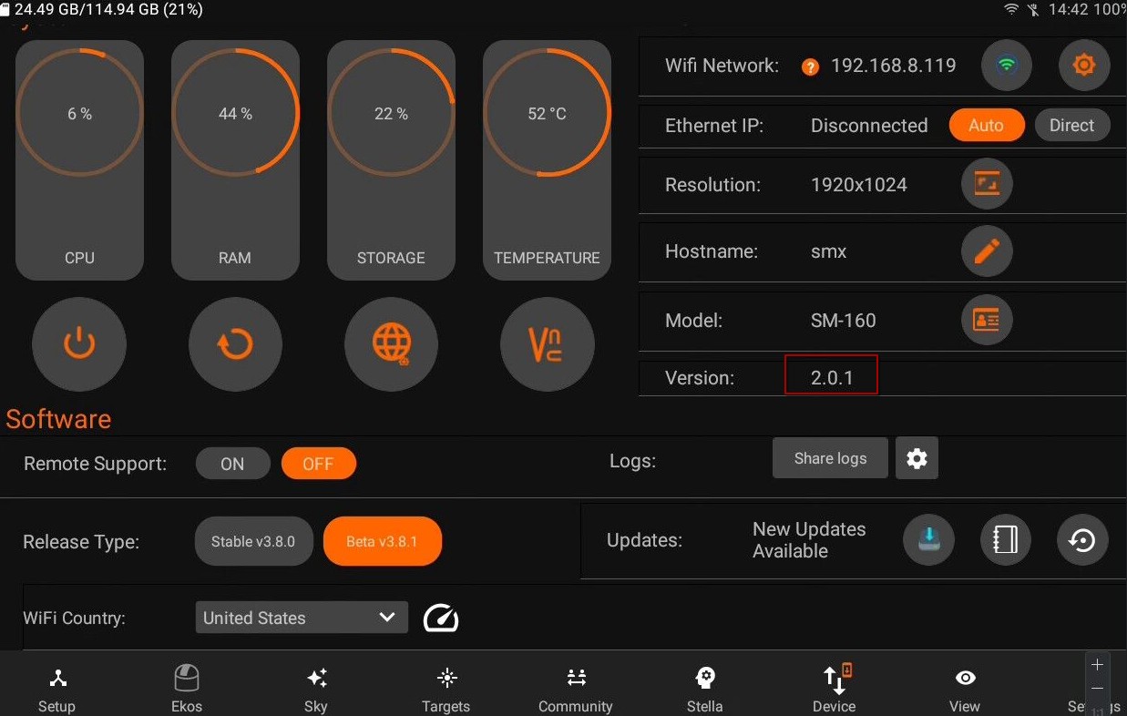
If no rollback version is available, the system displays “No previous versions available for Rollback.”
5.8.4.2. Remote Support
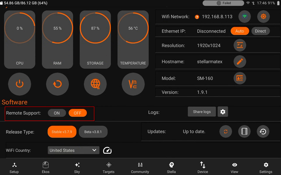
You can toggle Remote support if SM support asks for its access to investigate the issues you face. Once you toggle it ON, You wil see an ID.
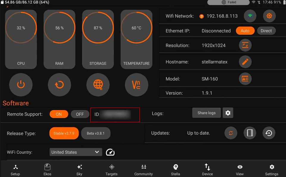
5.8.4.3. Cloud Backup & Restore
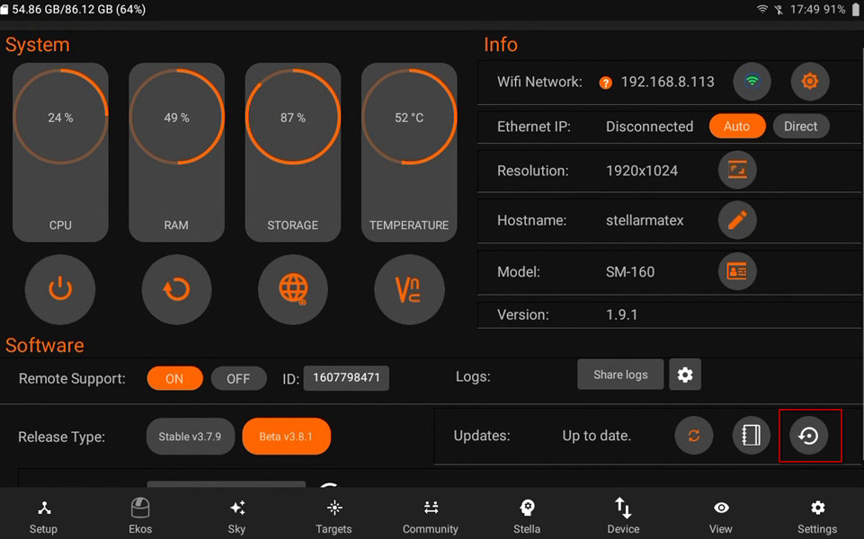
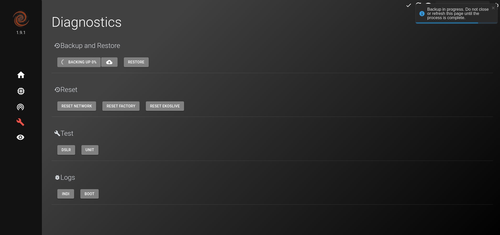
Back up StellarMate OS settings using the following options
Local Backup
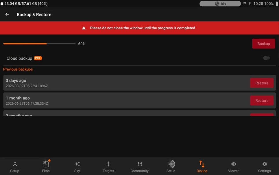
Save backup files directly inside StellarMate storage. All the backup files are located in ~/Documents/backup_files
Ability to download & upload offline backup files is planned for future release.
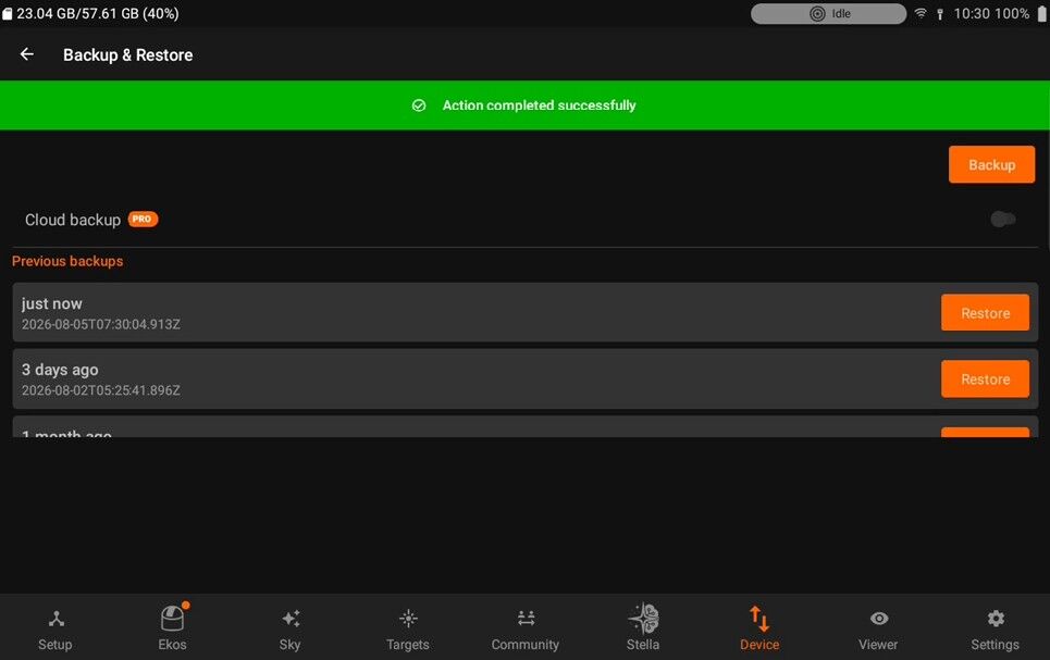
Cloud Backup
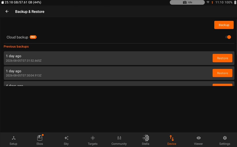
Cloud backup is only accessible to EkosLive Pro & Ultimate subscribers.
A total of three backups are stored and rotated in the cloud.
These files should be stored in the backup file.
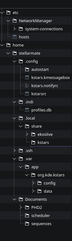
To restore from cloud
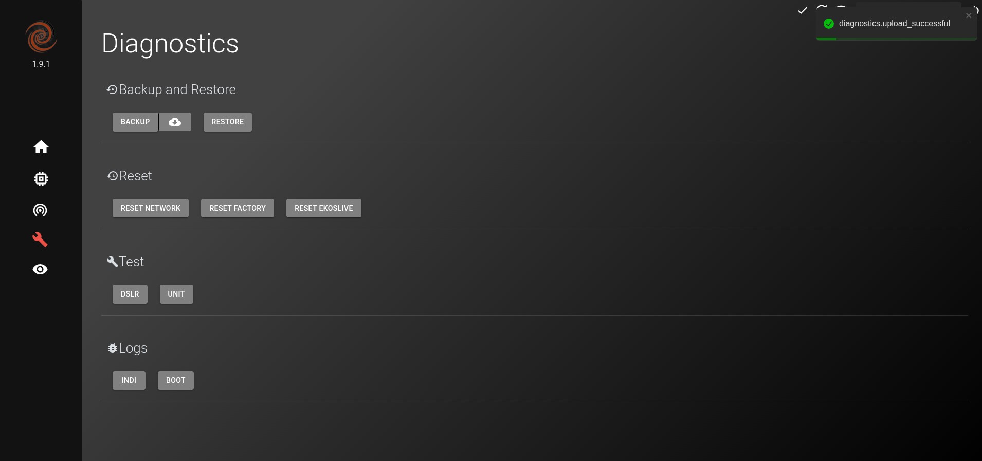
Select your backup file from cloud storage
Restore your data as needed.
5.8.4.4. Change Release
You can now easily switch between the Stable and Nightly release types. Stable: Contains the official, tested release updates. Nightly: Includes the latest, in-progress updates, which may contain experimental features or bug fixes.
If you encounter any issues with the Stable version, switch to Nightly to check if the issue has been resolved in the latest updates. If Nightly is not already installed on your StellarMate device, switching to Nightly will automatically download and install the latest version for you.
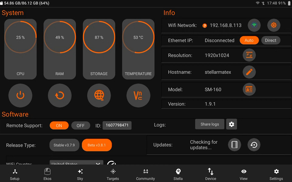
5.8.5. Logs
- Logs generated by StellarMate can be useful to diagnose system and/or driver issues. The logs are categorized into the following:
Driver logs for the camera, mounts, filter wheels, focuser..etc
Ekos logs for Capture, Focus, Align, Scheduler, and Guide modules.
System logs for the underlying system that includes boot and micro-services.
Only enable logs when planning to diagnose and submit an issue to StellarMate support. Logs can be quite verbose and may result in performance degradation so only use them when necessary.
- Submitting Logs
Toggle the necessary logs to reflect the issue being diagnosed by tapping the settings icon.
Start equipment profile and use the system normally to replicate the issue.
Tap Share Logs to send the logs to StellarMate servers.
Open a ticket with StellarMate support describing the issue. Please note the date and time when you submitted the logs so we may extract the logs relevant to the issue.

Ekos Logs
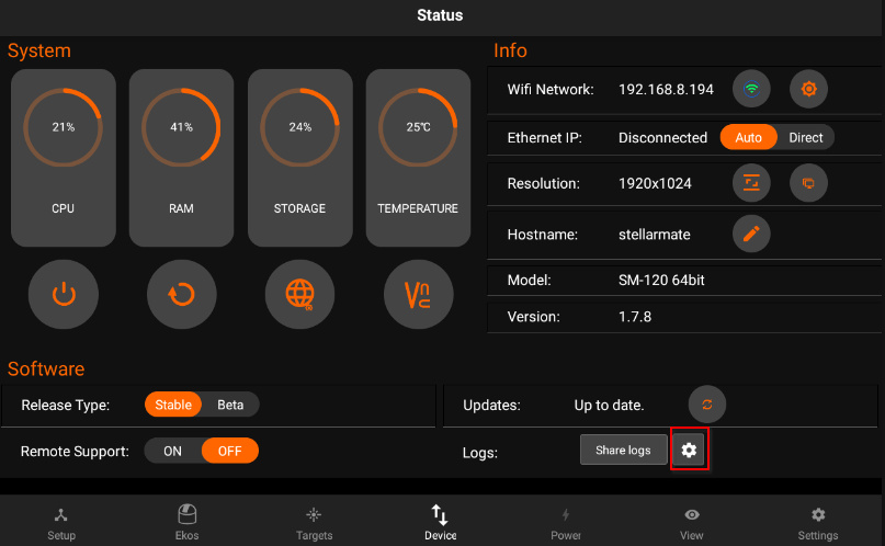
Enable logs to diagnose issues with Ekos and INDI. Only enable the necessary logs to help in diagnosing specific problems. Logs consume resources and may slow down the system. Turn off logs when no longer used.
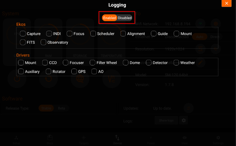
Network Benchmark tool measures real-time network performance to ensure reliable connectivity for your astronomical equipment. This is essential for stable remote operations, especially during long imaging sessions.
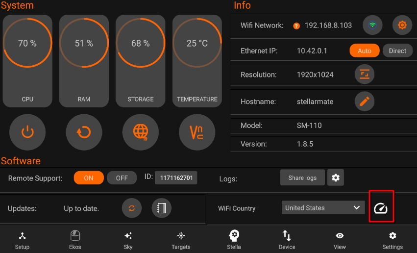
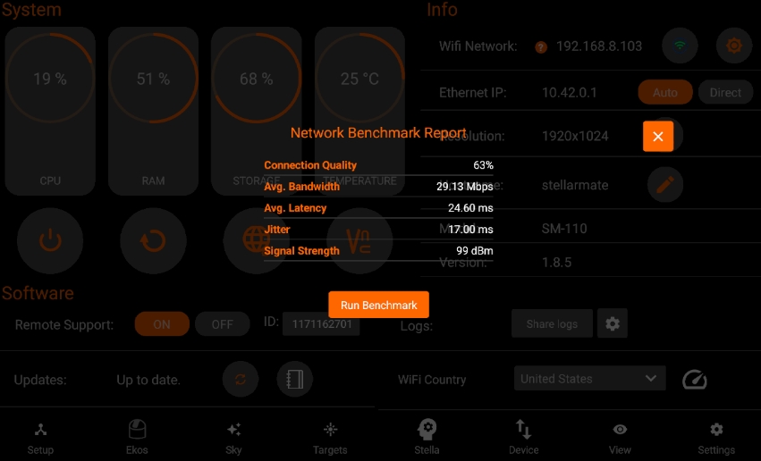
5.9. Power
Power tab provides access to StellarMate Pro power dashboard and environmental sensor measurements. The top half of the dashboard controls the DC, PWM, and variable voltage outputs, while the bottom half includes measurements, settings, and sensor widgets.
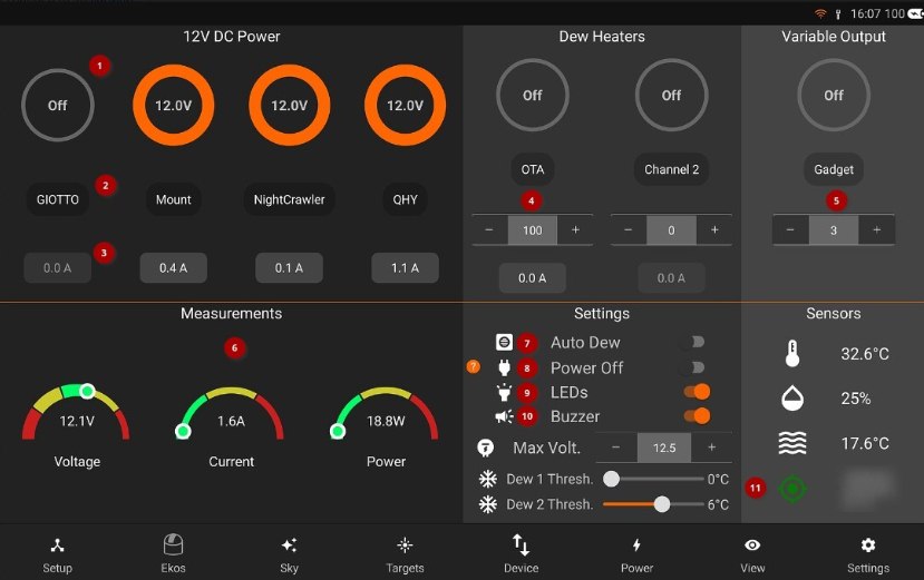
The following controls are available: 1. Toggle the power to each output. This setting is remembered on the next power cycle. 2. Assign a unique name to each output. 3. Measurement of the output voltage or current. 4. Set dew heater duty cycle from 0% to 100% 5. Voltage, Current, and Power measurements. 6. Power Off: Only power your equipment with Ekos equipment profile is running. When an equipment profile is stopped, power shall be switched off to all connected equipment. 9. Toggle All the unit LEDs on or off. This is remembered on the next power cycle. 10. Toggle buzzer 11. Activate GPS
Toggle Auto Dew. This feature requires an external environmental temperature & humidity sensor to calculate the dew point. If toggled, then the dew heater shall be turned on if the ambient temperature is within the dew point threshold as indicated in the settings. 1. Set variable voltage level (3 to 9 VDC) 2. Current Temperature and weather
GPS Lock indicator * Yellow: GPS lock in progress. * Green: GPS 3D lock successful. * Red: GPS lock failed.
5.10. View
The View tab displays online images saved on the cloud (requires EkosLive Pro subscription, refer to Resources section) and offline images captured on StellarMate. All metadata is preserved so you can sort and search your images at any time. You can toggle between Cloud or Offline images. You can also switch between Images / Videos.
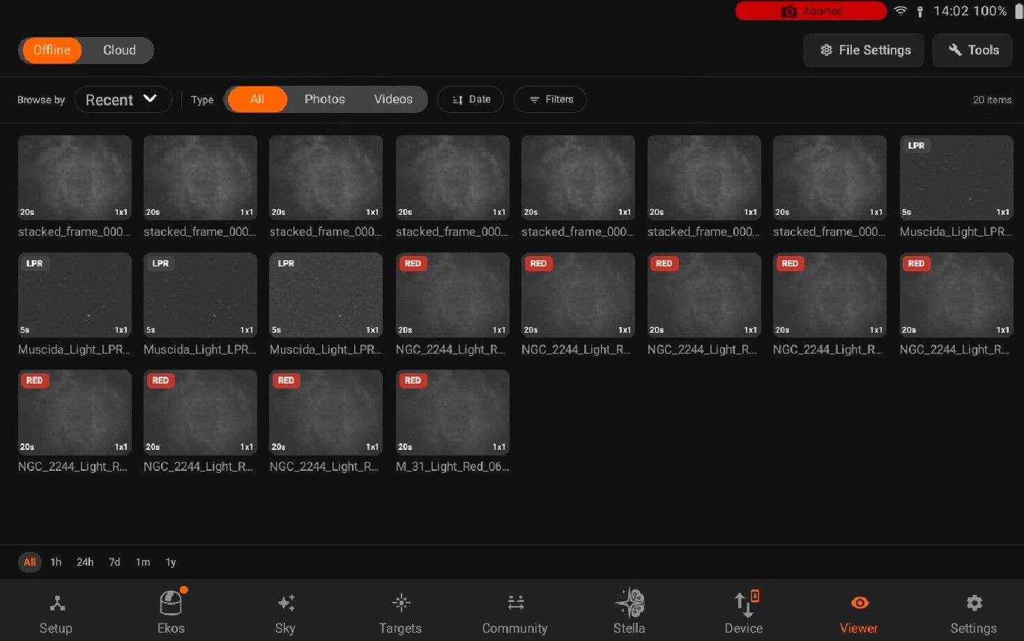
5.10.1. Images
Images are displayed in a grid view, Under each image there are badges for Filter, exposure duration, and binning. By default, all images are displayed in the grid without any filtering or sorting. Click on an image to view the full-size version which also provides further actions such as export and export. You can filter the images by using the left panel. Changing the Field, allows you to select to filter using different options based on the chosen condition. Advanced search is available from the left panel. Select the condition that must be met from the metadata fields. You may add multiple conditions to further restrict the search.
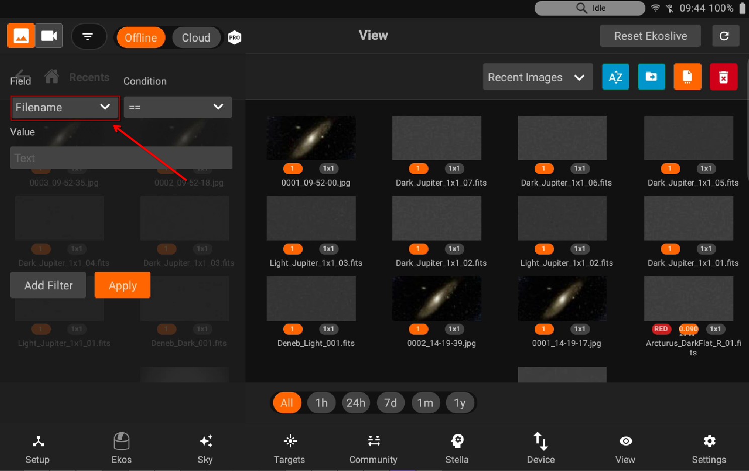
StellarMate aggregates images in Virtual Folders based on the selected Virtual Group:
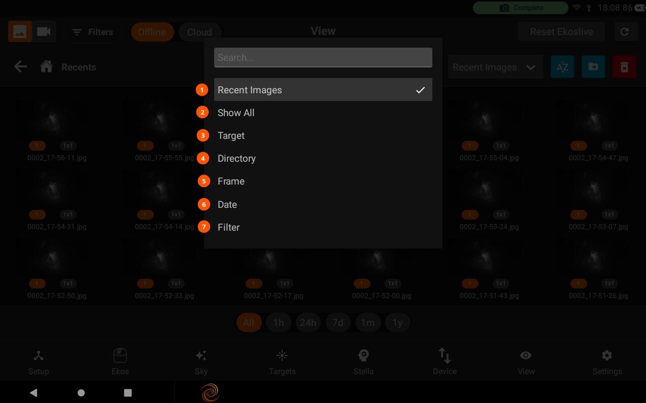
Recent Images: Shows 20 latest images captured.
Show all Images: Show all directories & images under /home/stellarmate/Pictures.
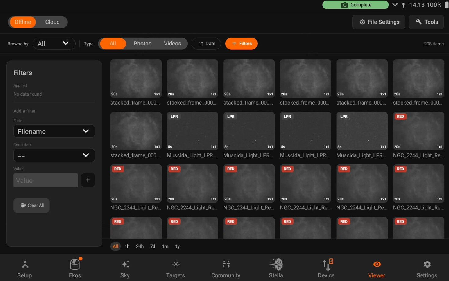
Target: Group images by each unique target together regardless of where they are physically located on the device.
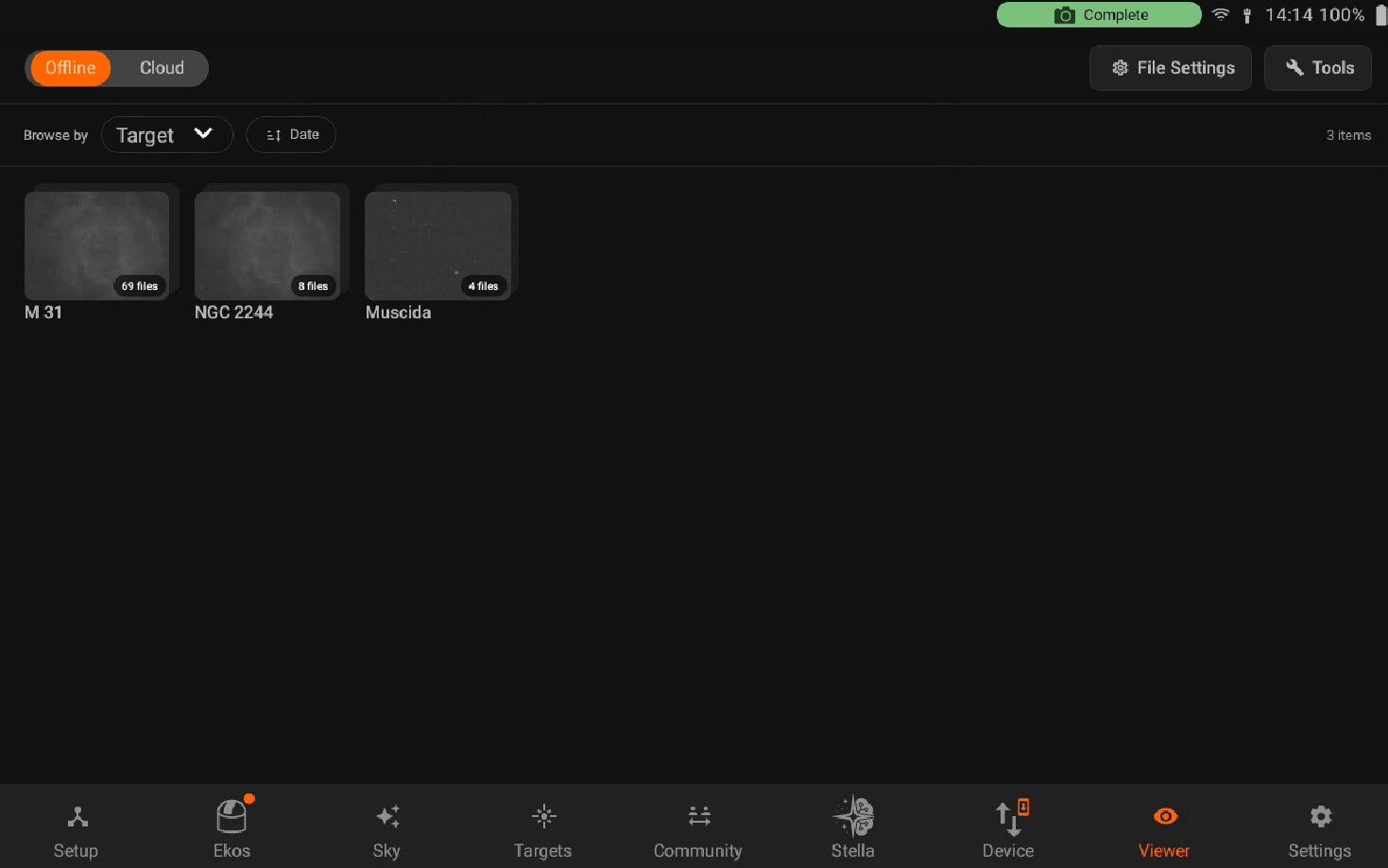
Directory (Default): This is similar to a traditional File Explorer where images are grouped by directory on StellarMate.
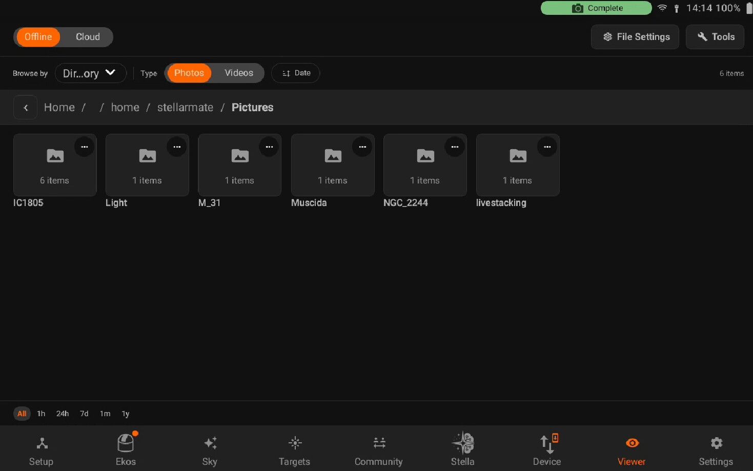
You can now also delete the directories. In order to delete a directory, just visit the directory and you will see the delete icon button beside the directory locatory to delete all images in a directory.
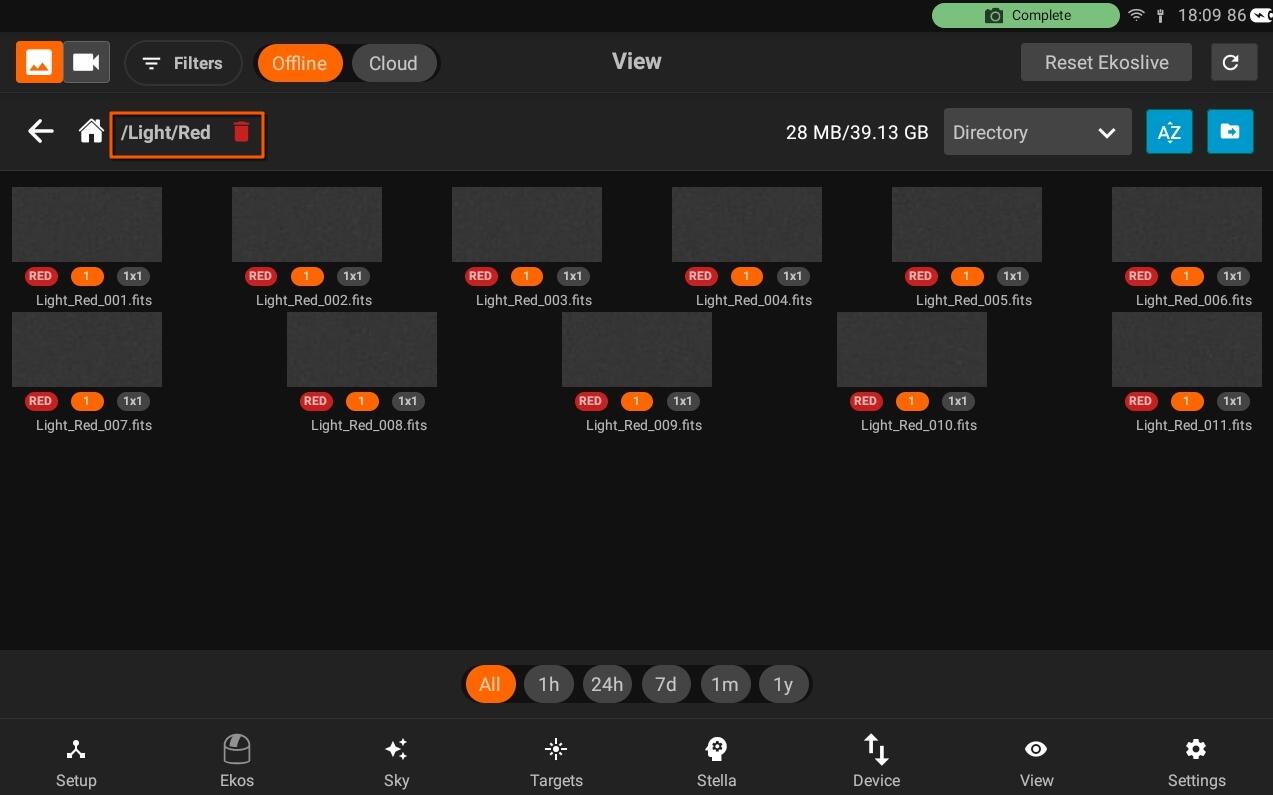
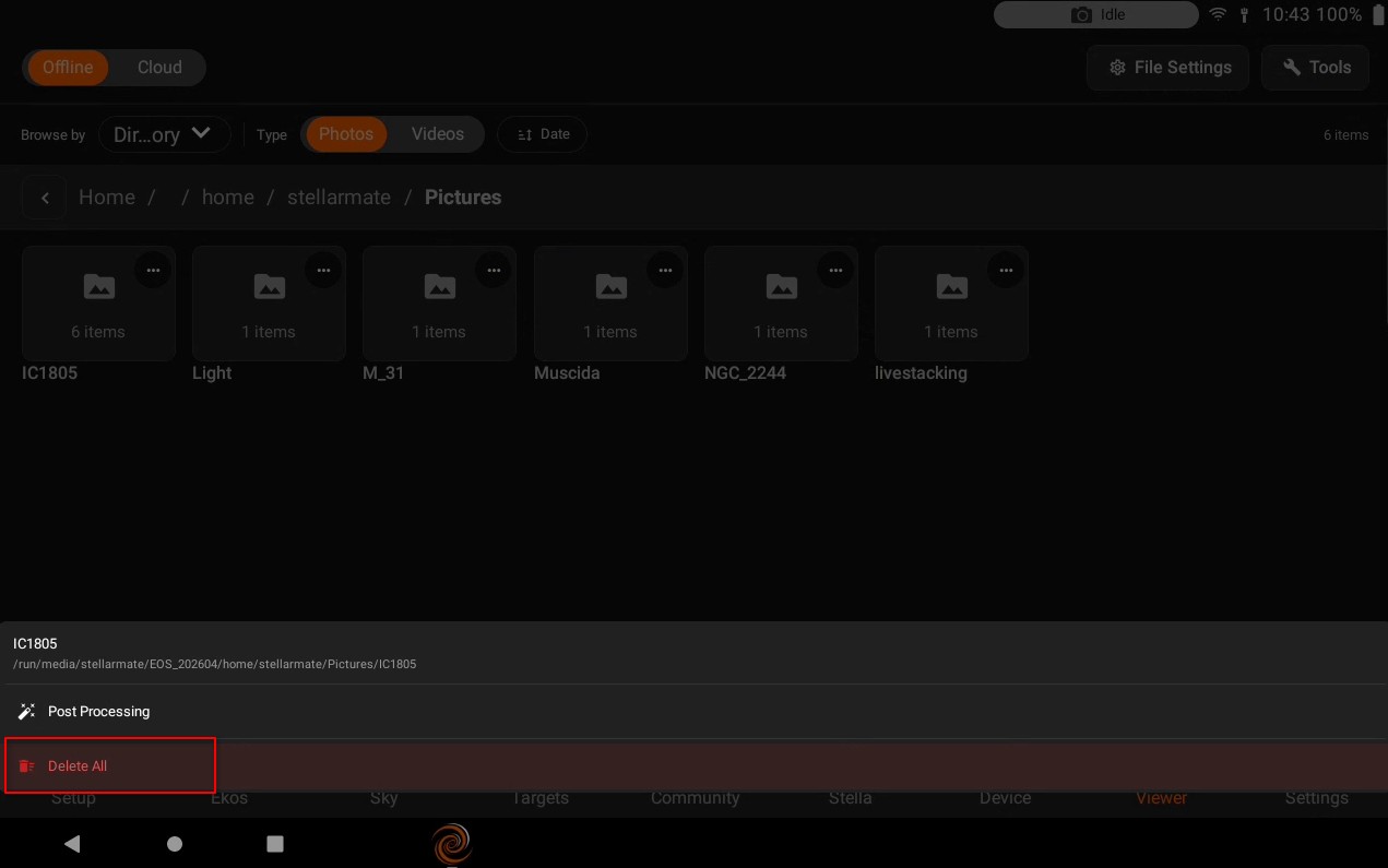
Frame: Group images by each unique frame type (i.e. Light, Bias..etc).

Date: Group images by date whereas images captured on the same day are grouped together.
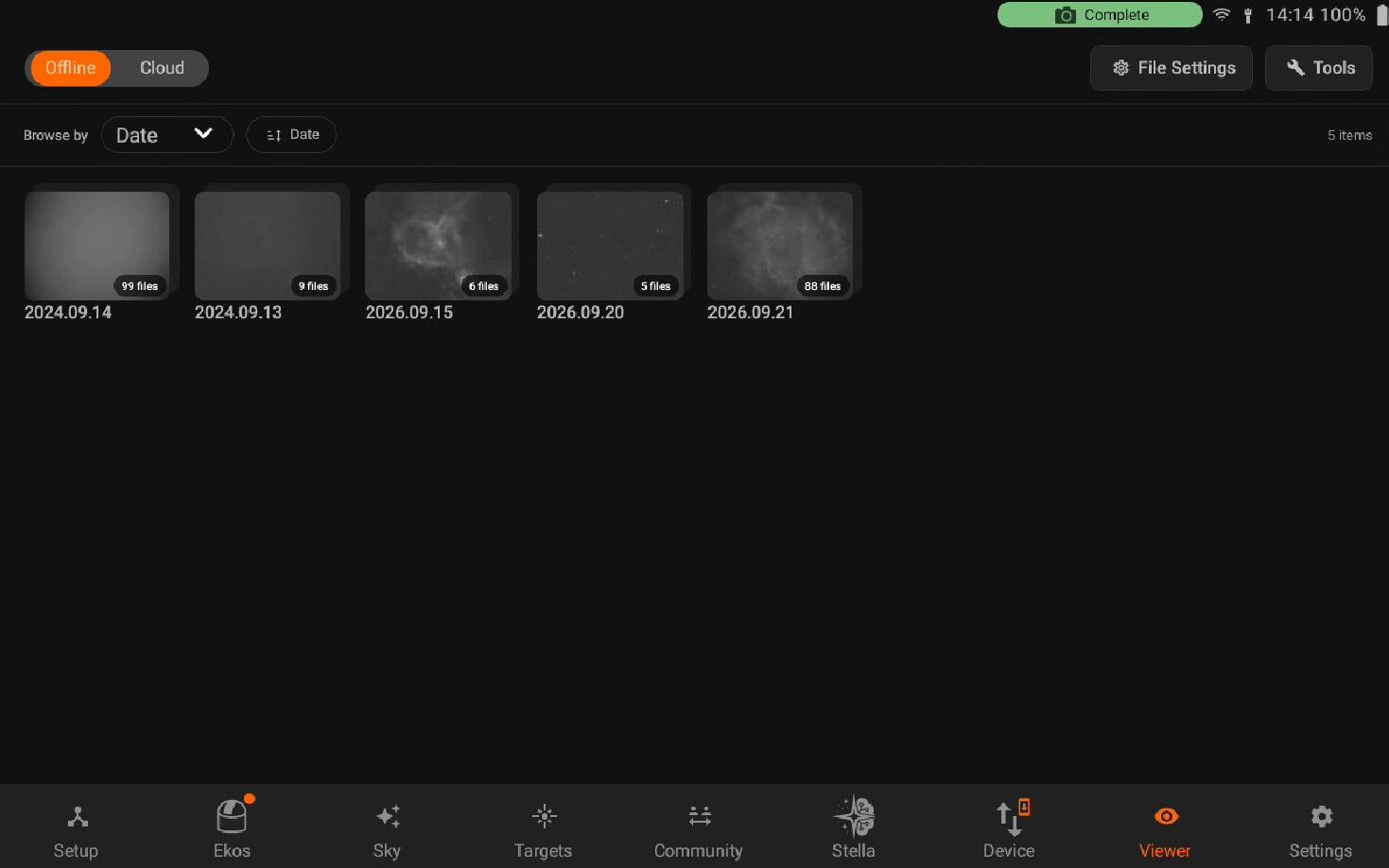
Per filter: Images are shown per filter. Those folder directories are Virtual folders.
Images can be further filtered chronologically by tapping on the bottom chrono selector. By default, images captured at all times are displayed. To filter only recent images, tap the chrono selector. For example, tapping 1H would only show images captured within the last hour.

You can view the image in full size by click on a specifc image. Below the list of images which are in that Directory are shown. On each image click, the image and it’s information will be loaded. You can also download and delete the selected image on the right side. To view detailed metadata, tap the top-left Info button, the information of a specific image is displayed as illustrated below.
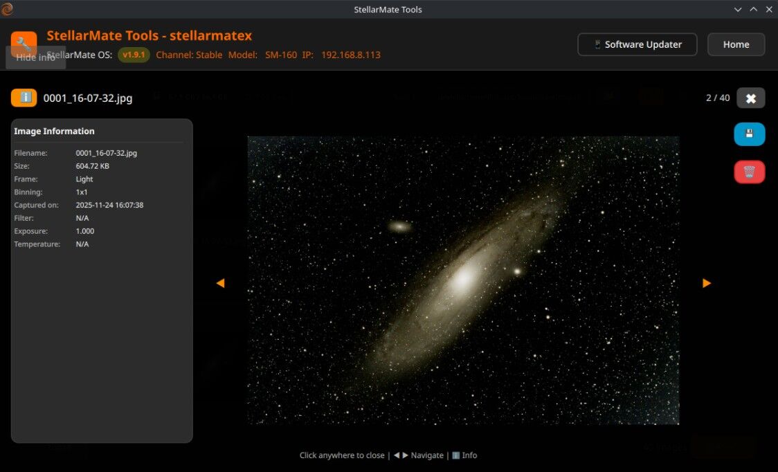
Sort: It allows you to sort the images according to different options which includes, Name, date, Size, frame, Filter and Exposure.
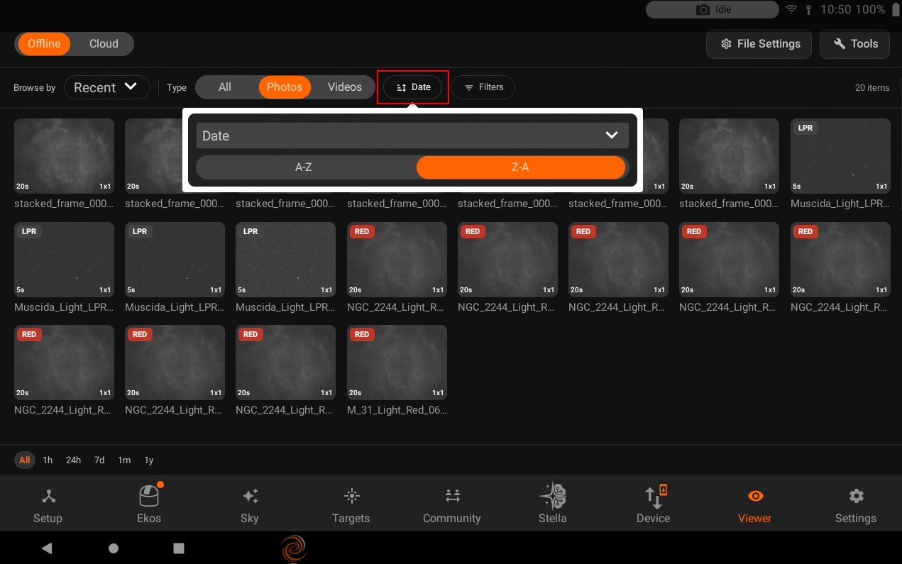
Delete all: Deleting all images will delete all the images exists in the specifc directory. i.e If you are in Per filters option and RED filter directory. It will only delete your images within RED directory virtual folder.
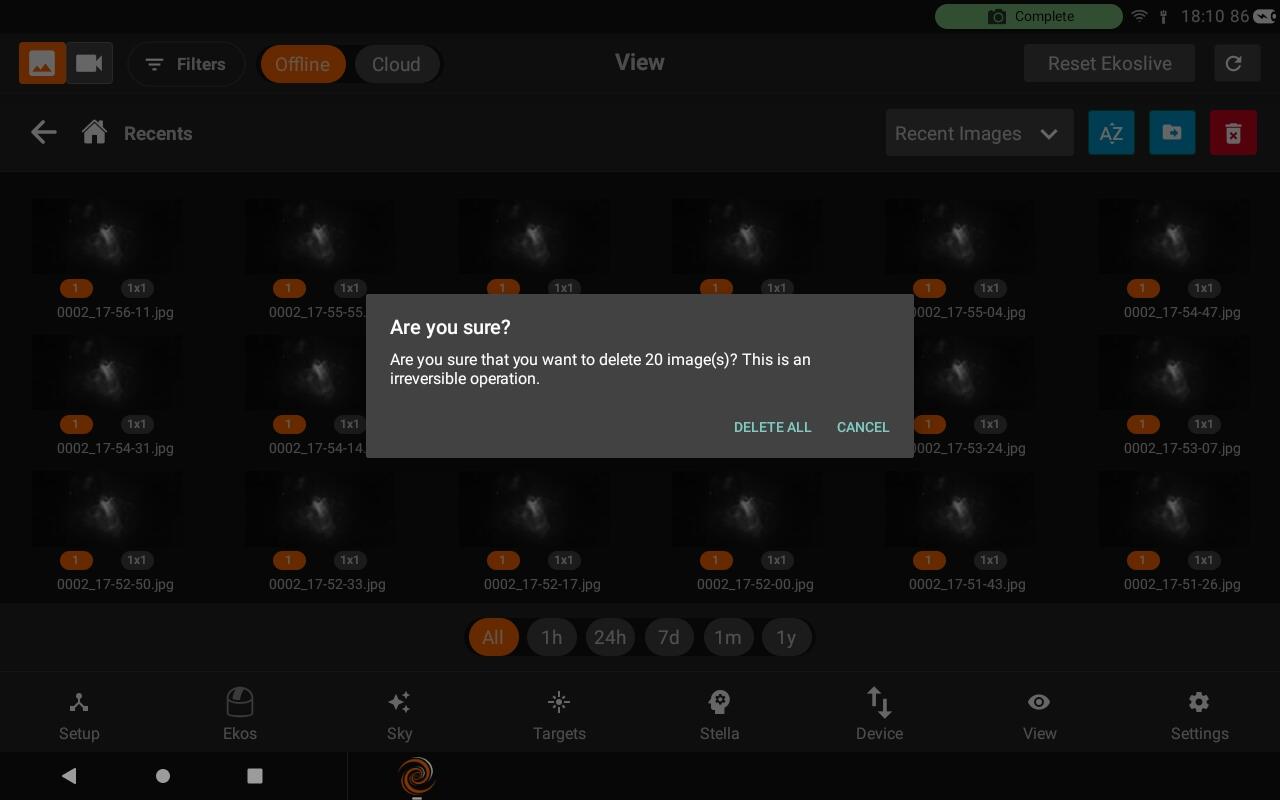
5.10.2. Videos
In videos section, you can view folders and files under “/Videos” directory. Directory name and it’s is displayed under the folder/file.
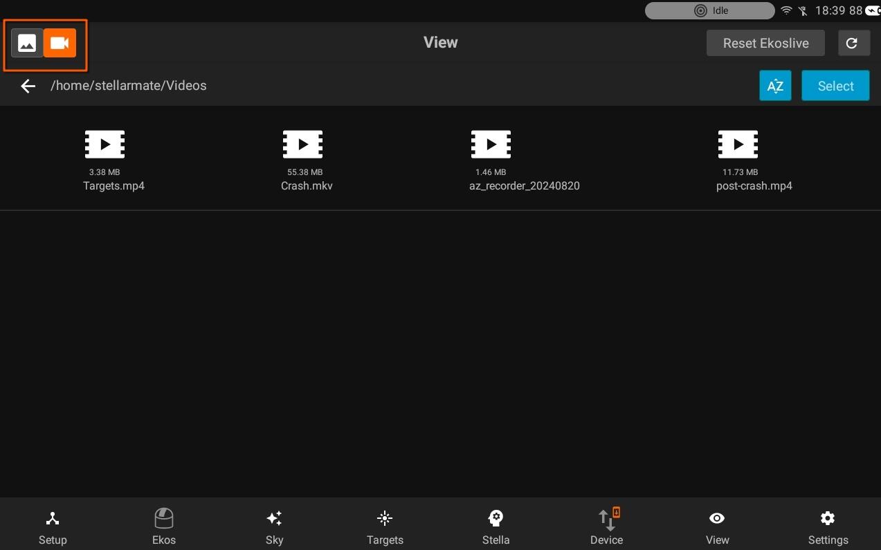
You can press on the select button, once selected check the video file info on the right side.
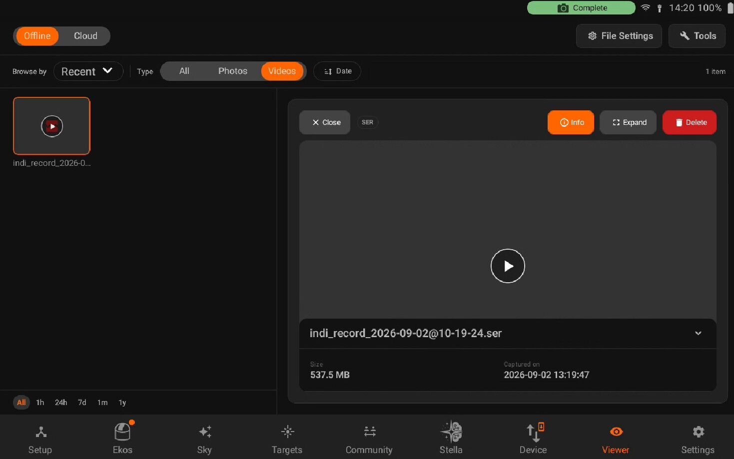
Expand to toggle the full view.
Delete delete selected file
5.10.3. Transfer Images
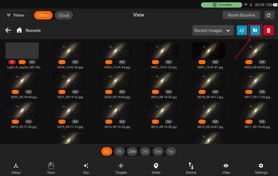
Synchronizing your images to an external USB thumb drive is now very easy! From the View tab, select the desired external USB drive and transfer all your images.
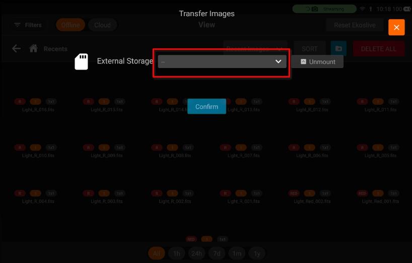
For subsequent transfers, the system only transfers the new images since your last sync.
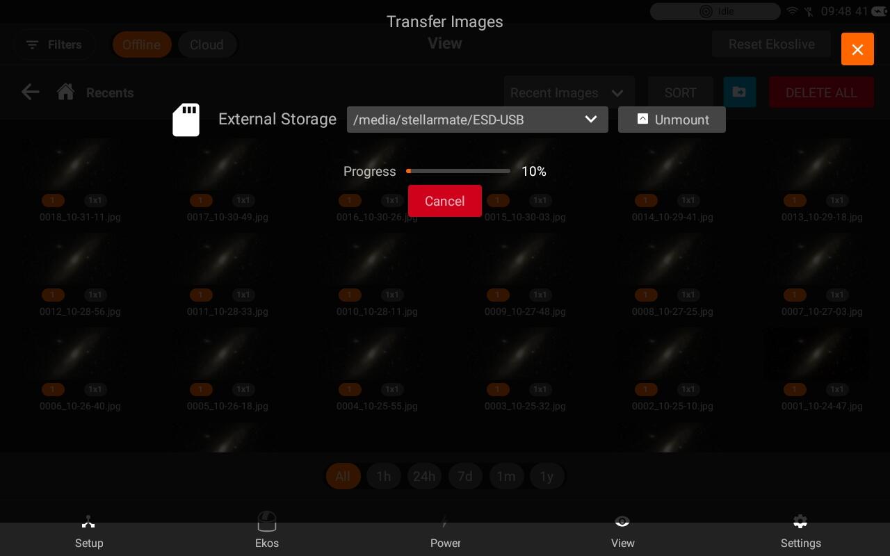
5.10.4. Post Processing
Post Processing lets you calibrate, stack, and edit a set of captured sub-frames directly from the StellarMate app, without needing a desktop computer. It runs on StellarMate itself (the same stacking/editing engine used by KStars) and walks you through a wizard of steps: Calibrate, Stack, Combine, Crop, Background Extraction, Color Calibration, Denoise, Stretch, Saturation, and Contrast. Only available for images stored locally on your StellarMate device (not the Cloud images).
Opening Post Processing
Post Processing can be accessed either via the Tools menu or by changing the filter to Directory, then tapping on the directory to launch it. The directory should contain all your light and calibration (dark/bias/flat) frames and the App would automatically assigned each file to their respective category for calibration. You can also override this and specify your own master files if they exist outside the selected directory.
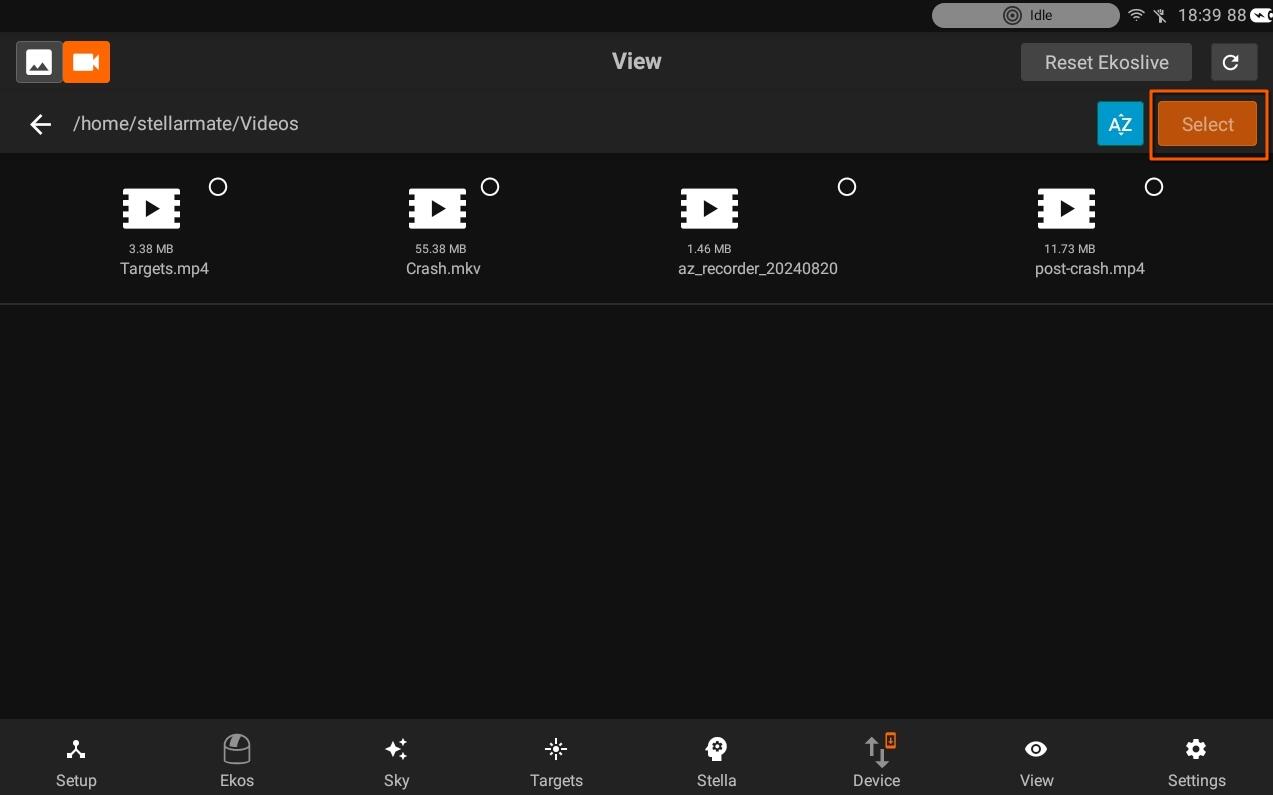
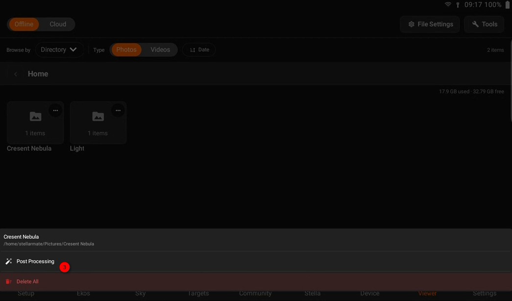
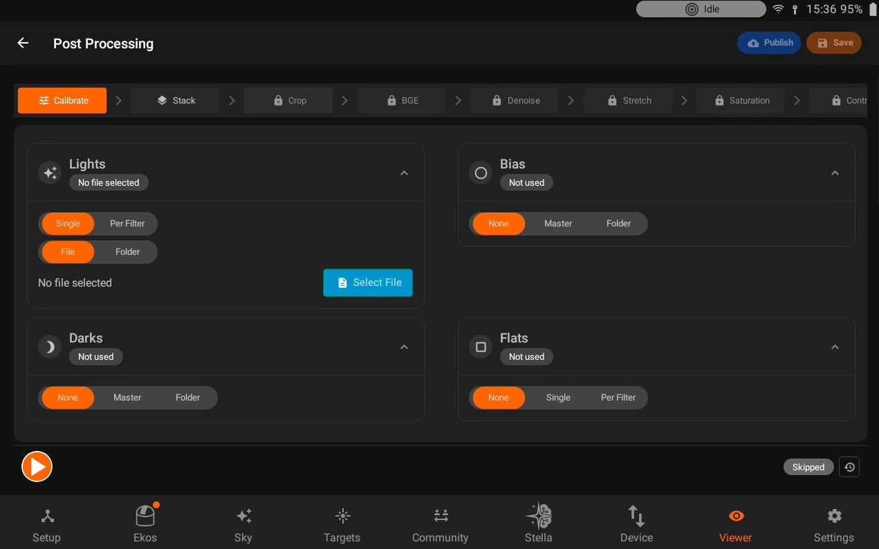
From the View tab, open the Tools menu on the Gallery screen and select Post Processing. You can also long-press a directory tile and choose to post-process that folder directly. For best results, the wizard expects all the lights and calibration frames under that folder. The App automatically scans the folder in the background to pre-fill the Lights (and, when it can find them, Bias/Dark/Flat) sources on the Calibrate tab.
If StellarMate finds leftover results from a previous, interrupted post-processing run on the same target, it asks whether to pick up where you left off:
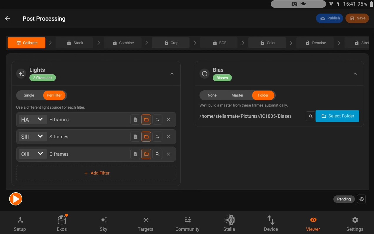
Resume - reloads the previously built masters/stacks and marks those steps Done, then jumps you to the first step that still needs attention.
Start Fresh - discards the leftover files and begins a clean run.
Screen layout
Across the top of the wizard is a row of step tabs (Calibrate, Stack, Combine, Crop, BGE, Color, Denoise, Stretch, Saturation, Contrast), each shown as an icon with a short label. A tab is:
Active - the step you’re currently viewing.
Done - the step has already run.
Skipped - you jumped past it, or it isn’t needed for this data.
Locked (padlock icon) - a required earlier step (Calibrate, Stack, or Combine) hasn’t finished yet, so this step can’t be opened.
Combine only appears for multi-filter (narrowband/RGB) data; Color Calibration only appears for color/multi-channel data. There is no explicit “Skip” button - tapping ahead to a later, unlocked tab automatically marks any optional steps you passed over as Skipped. Calibrate, Stack, and Combine are mandatory and can’t be skipped this way.
Most steps show a two-pane layout: a settings sidebar on the left (which you can collapse for an unobstructed view using the small arrow in the corner) and an image preview on the right showing the current working image. Once a step that edits pixels has actually run, a Before / After switch appears over the preview so you can compare the result against the image right before that step ran. For multi-filter Stack runs, a row of small filter pills above the preview lets you pick which channel’s stack to look at.
Each step’s sidebar ends with the same action row:
A Run button starts that step with its current settings (for a grouped multi-filter Stack, this runs every channel in sequence). It becomes a Stop button while a cancellable step is in progress, alongside a progress bar.
Once a step is Done, a Redo button lets you re-run it, and an Undo button reverts its most recent result back to Pending.
A status badge (Pending / Running / Done / Skipped / Failed) and a reset icon (restore that step’s own settings to their defaults) sit on the right.
Leaving the wizard while a step has run or is running asks you to confirm, since it stops any in-progress work and removes temporary files.
Calibrate
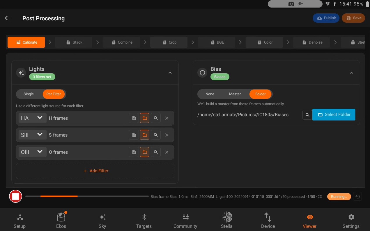
The first tab, laid out as four collapsible cards:
Lights - choose Single (one folder or file of light subs) or Per Filter (a separate light source for each filter, added with an Add Filter row: filter name, then a file or folder picker). A folder or file next to any source can be inspected (magnifying-glass icon) to see how many FITS files it contains and a breakdown by exposure/filter/binning/frame type.
Bias and Darks - each can be None, a Master file you pick directly, or a Folder of raw subs that StellarMate will combine into a master automatically when the step runs.
Flats - None, Single (one flat, Master or Folder, used for every filter), or Per Filter (a Master or Folder per filter, recommended if your optical train changes between filters).
After successful Calibration, Master files for Darks, Biases and Flats are generated. You can double check under your output folder directory.
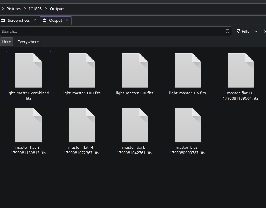
Stack
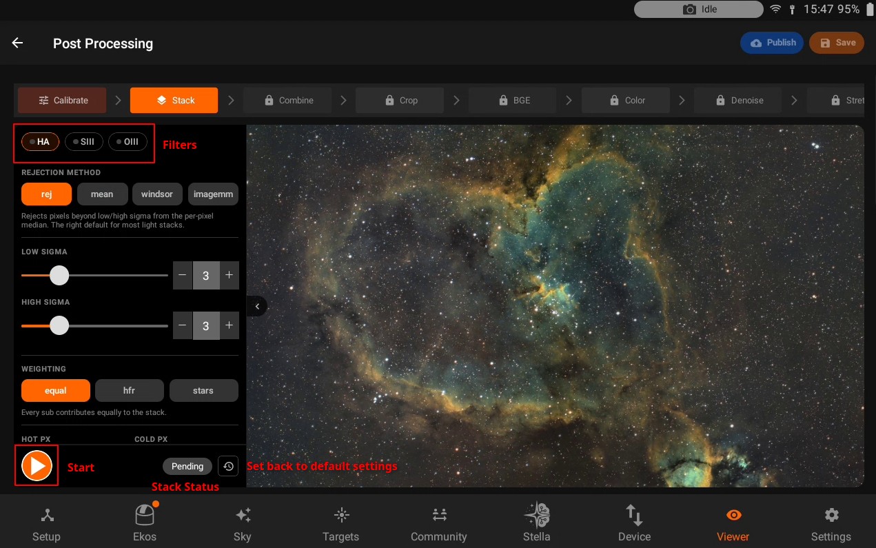
For Per Filter Lights with more than one filter, Stack becomes one grouped tab covering every channel; otherwise there’s a single stack.
Rejection Method - rej (sigma-clip against the per-pixel median, the recommended default), mean (no rejection at all - a trail or cosmic ray in a single sub survives), windsor (clamps outliers instead of excluding them, more robust with few subs), or imagemm.
Low Sigma / High Sigma - clipping thresholds (hidden when Rejection Method is mean).
Weighting - equal, hfr (sharper subs count more), or stars (subs with more detected stars count more).
Hot Px / Cold Px - toggles to correct stuck bright or dark sensor pixels before stacking.
Align Reference Frame - optionally pick an explicit file for every sub to align against; if left unset, StellarMate plate-solves against the subs themselves.
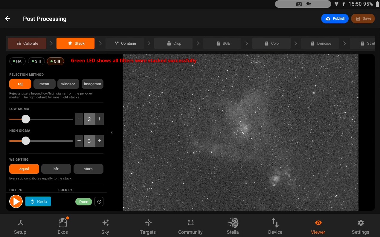
If no sub can be plate-solved, the subs are combined without alignment and a warning is shown, since stars may look smeared from ordinary tracking drift.
Combine
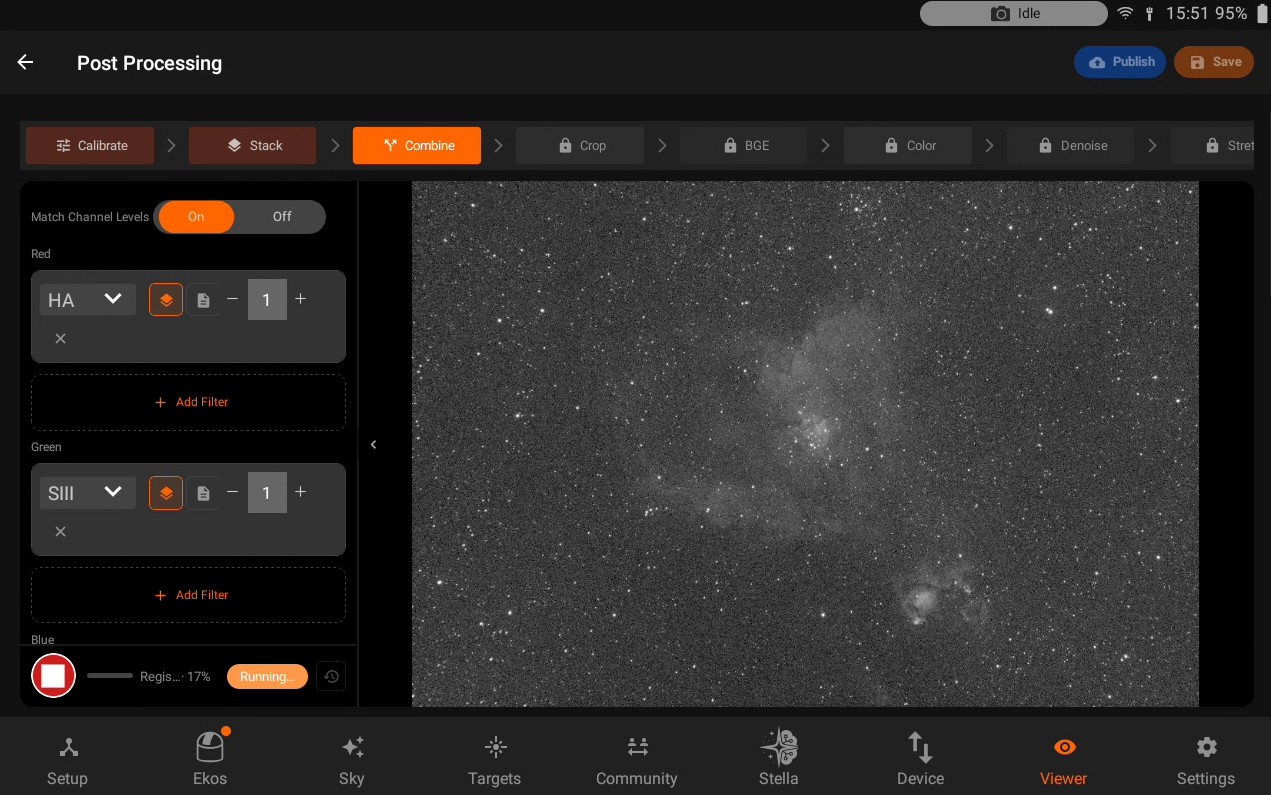
Only shown for multi-filter data. Combines the individually stacked channels (or previously saved master files) into a color image - the standard way to build narrowband palettes like SHO or HOO as well as ordinary RGB or LRGB.
Match Channel Levels - equalizes brightness across channels before blending, so mismatched sky background between filters doesn’t tint the result.
Red, Green, and Blue sections, each a list of rows summed into that channel - useful for mixed palettes (e.g. Green = 0.7 x OIII + 0.3 x Halpha). Each row can pull from a channel that was just stacked, or from a saved master file, and carries its own weight (default 1.0, not renormalized). Rows are added with Add Filter and removed individually.
Running Combine requires at least one row assigned to each of Red, Green, and Blue.
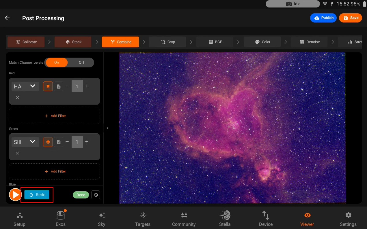
Crop
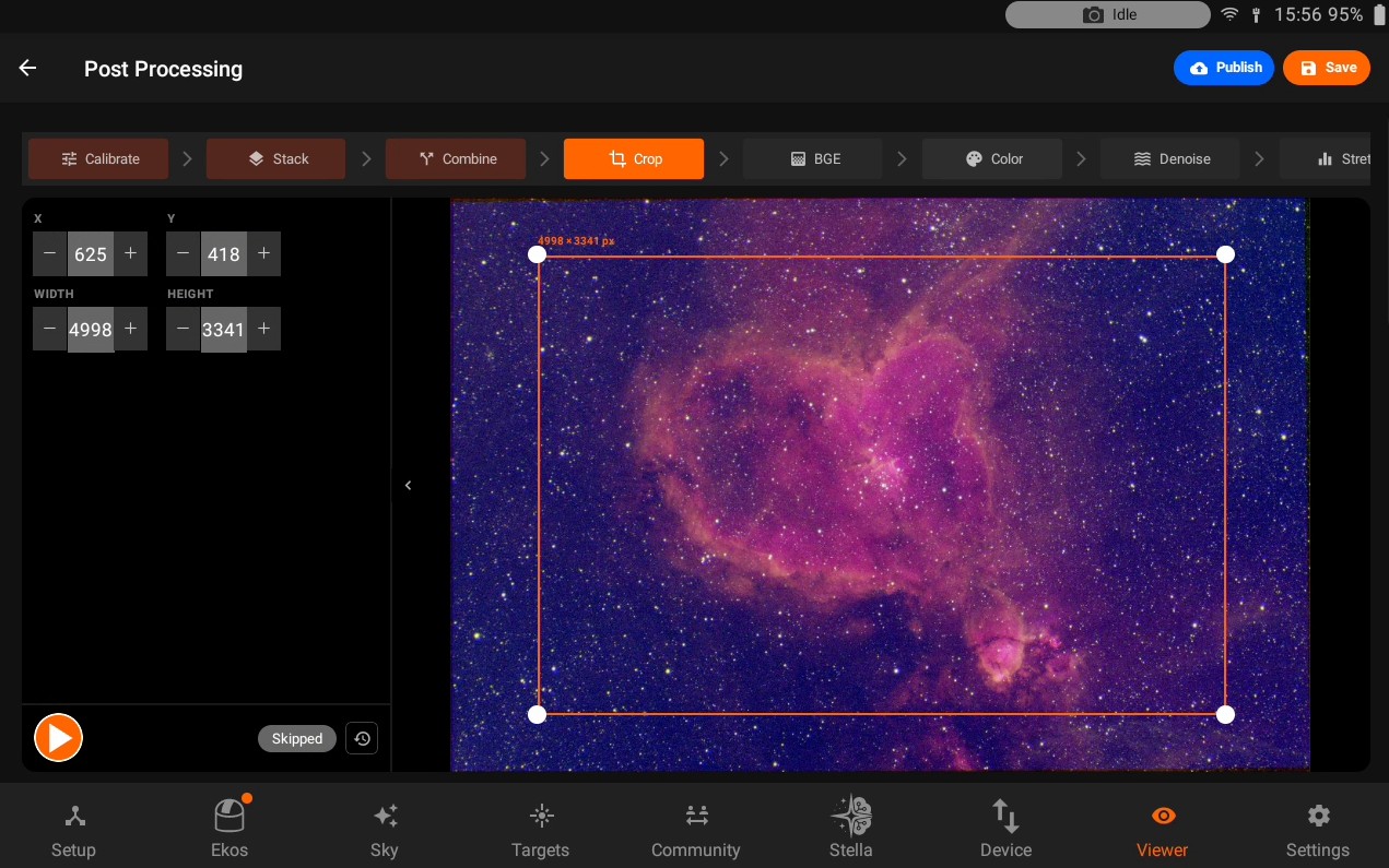
Skipped by default. A draggable, resizable rectangle appears directly over the image preview - drag the middle to move it, or a corner handle to resize it; a floating label shows the selected size in pixels. The same region is also shown as X, Y, Width, and Height fields in the sidebar, kept in sync with the on-image box. Running Crop requires a width and height greater than zero.
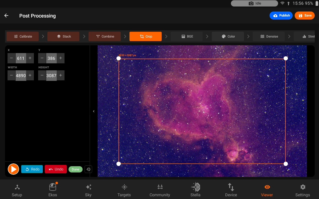
Background Extraction (BGE)
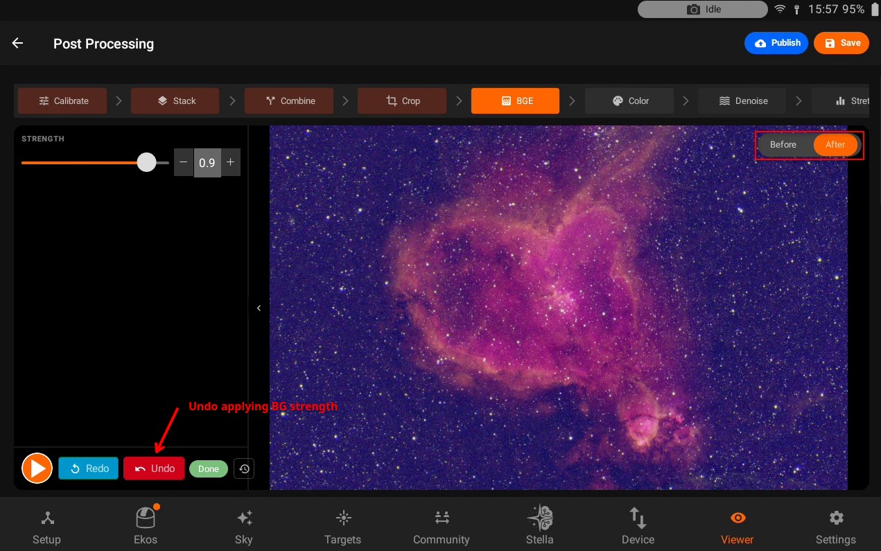
A single Strength slider (0-1, default 0.3) that removes gradients and uneven background glow from the still-linear image. Do not use it on images where a large part of it is filled with nebulosity.
Color Calibration
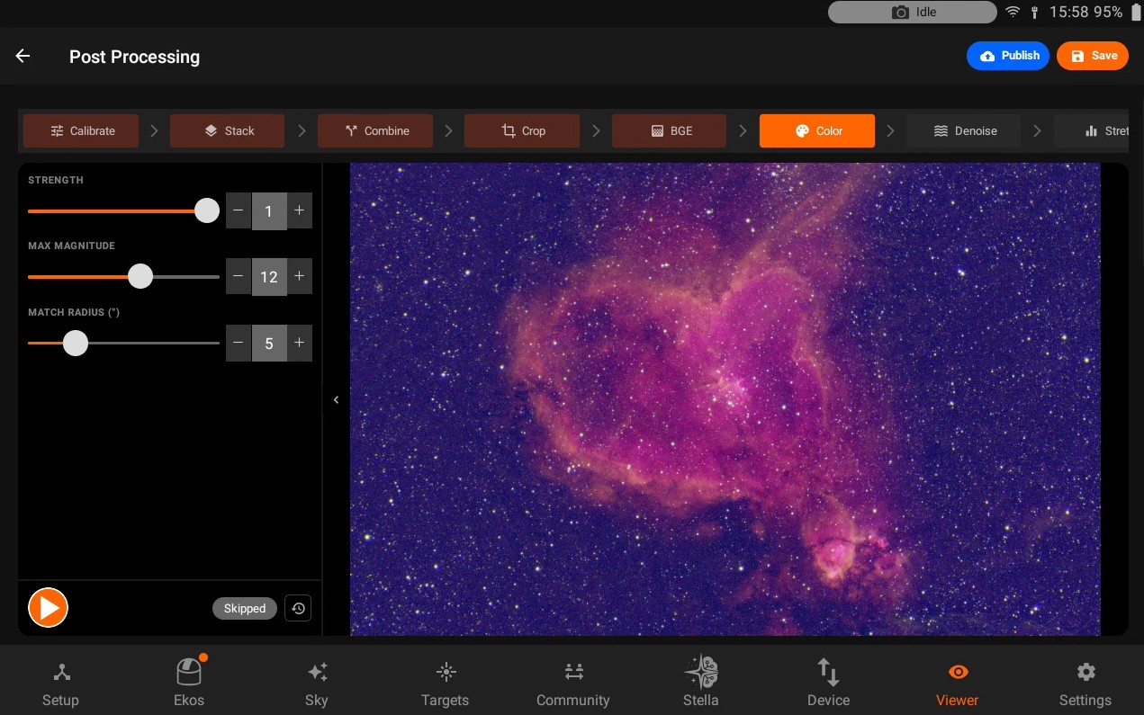
Only shown for color/multi-channel data, and skipped by default. Corrects star colors photometrically against a star catalog, and should be run right after Background Extraction, before Denoise or Stretch.
Strength (0-1, default 1.0)
Max Magnitude - faintest catalog star used for matching (6-16, default 12.0)
Match Radius (“) - matching tolerance in arcseconds (1-20, default 5.0)
After running, a result line reports how many stars were detected and how many were corrected.
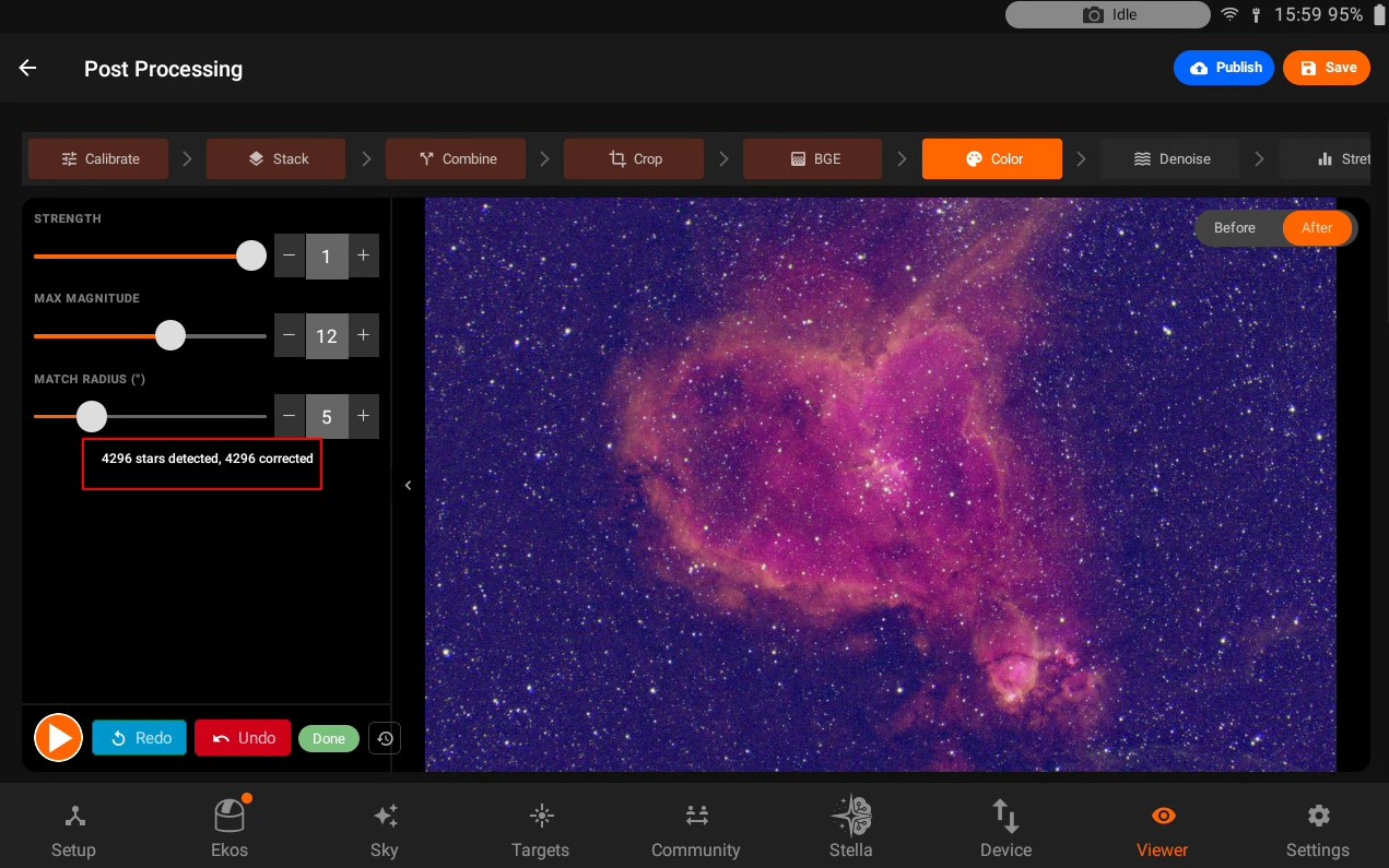
Denoise
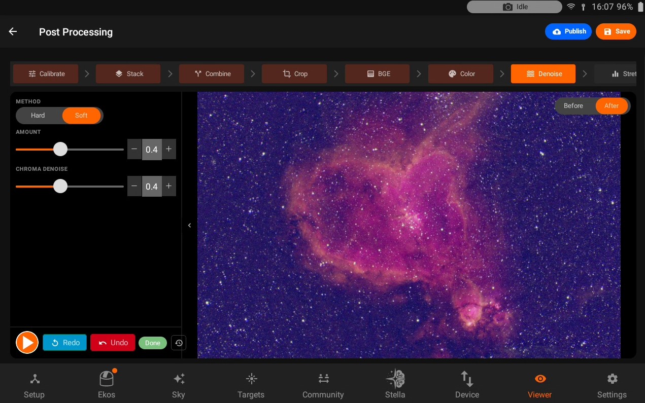
Method - Hard (binary threshold) or Soft (smoother shrinkage, default).
Amount (0-1, default 0.4).
Chroma Denoise (0-1, default 0.4) - reduces color noise independently of luminance noise.
Stretch
Converts the image from linear data into a normal-looking picture, with an optional tone curve on top.
Mode - Auto (an autostretch, optionally refined by a curve) or Manual (no autostretch - the curve itself defines the stretch, evaluated against the image’s own brightness range).
In Auto mode: Background (target background level, default 0.25) and Clipping (shadow clipping, default 2.8), plus Link Channels and Neutralize Background toggles (both on by default) for keeping narrowband composites color-neutral.
Curve - Off (Auto mode only, pure autostretch), Curve (one shared curve), or RGB (independent curves per channel, for color data).
The curve editor shows a faint histogram of the image behind a draggable tone curve: tap an empty area to add a point, drag a point to move it (the two endpoint handles only move vertically, adjusting black/white point), and long-press a point to delete it. A Reset link restores a sensible default curve for the current mode. In RGB mode, small Red/Green/Blue pills switch which channel’s curve you’re editing, with the other two shown faintly for reference. Switching between Auto and Manual resets the curve, since a curve authored for one doesn’t carry over correctly to the other.
Saturation
A single Saturation slider (0-2, default 1.0).
Contrast
A single Contrast slider (0-2, default 1.0) - the last step in the pipeline.
Finishing up
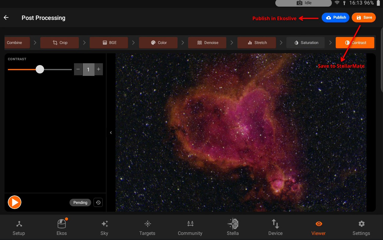
Two buttons sit in the header, available once there’s an image to work with:
Save - enabled once every mandatory step (Calibrate if needed, every channel’s Stack, and Combine for multi-filter data) is Done. Saves the current working image to your library and returns you to the Gallery.
Publish - uploads the current result to EkosLive. Opens a dialog summarizing your observatory/equipment profile and any detected filters with their integration time, where you set a title (required) and optional description before publishing.
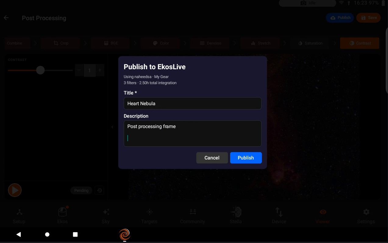
5.11. Settings
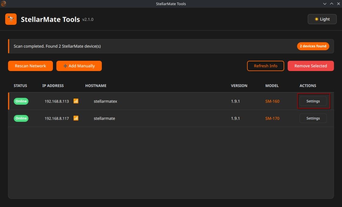
General Settings
- Language: Supported Languages are:
English (Default)
French
Spanish
German
Chinese
Japanese
You can help with translating the StellarMate App. Visit the StellarMate App Translations Github repo <https://github.com/knro/smtranslation>_ for more information.
Sky Map Scheme: Change the Sky Map color scheme.
English (Default)
French
Spanish
German
Chinese
Japanese
StellarMate App theme: Please note that if the App theme is changed to Night this automatically switches Sky Map theme as well to Night Theme: Overall App theme. StellarMate App provides two themes: Dark (default) and Night. When night is toggled, all controls are rendered using a red hue to help with eye adaptations in the dark.
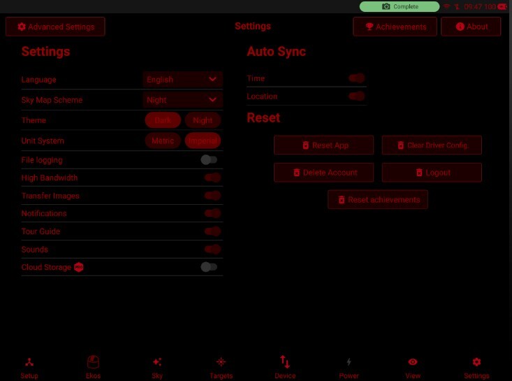
Unit System: Unit system used for weather related information. All other units in the App use the Metric System by default unless explicitly mentioned.
Notifications: Toggle in-App notifications.
Tour Guide: Toggle to re-enable the App Tour Guide.
Sounds: Enable sound notifications, the following events trigger a sound notification:
When the capture sequence is aborted or completed
When the Polar Alignment mount position changes
Current Plan User’s current active plan.
Cloud Storage: Toggle saving images in the cloud. Required an active EkosLive Pro Subscription. StellarMate unit needs to have a reliable and fast internet connection for the cloud storage to reliably work. Sequence images are compressed and uploaded to the cloud where they can be viewed at any time from either the App or EkosLive online portal. All the image metadata is preserved in the process which can help in filtering, organizing, and searching for images at any time.
Pro users** can enable the Push notifications. If they are enabled, users will be able to get the notifications on their Tablet device.
Users who are not subscribed to EkosLive Pro will see a pop up as shown below:
In order to subscribe, you can follow the link here.
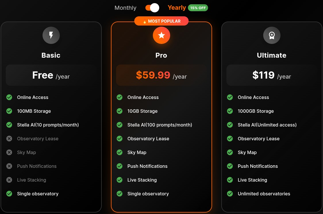
Stella Assistant Disable Stella in Ekos
Push Notifications Use Pushoverlay Notifications
Cloud Backup Backup your SM OS file and restore for later.
Auto-sync Time and Location: When the SM App is started, it syncs tablets time and send to Ekos.
Reset App:
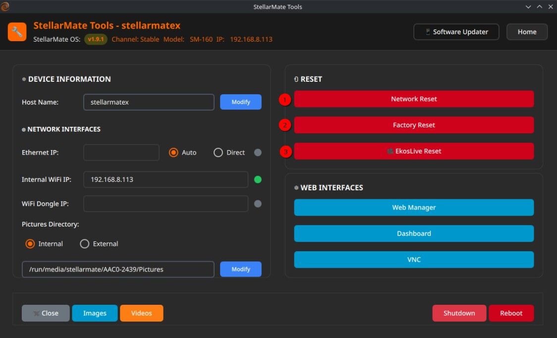
Reset App and start from scratch.
Reset Ekoslive and regenerate the images
Reset Desktop if your desktop is messed up
Reset Network to set the default network settings
Clear Driver Configuration files
Factory reset data
Delete Account: Delete your account in stellarmate.com. Once deleted, the account and associated data will be permanently deleted.
Logout: Sign out of StellarMate App. Only use this if you need to sign in using a different accounts.
5.11.1. Achievements
Once you complete the Achievement, Achievement earned pop up is displayed. Which includes the title of the Achievements and it’s points. Few of the common achievements are:
Capture a preview:
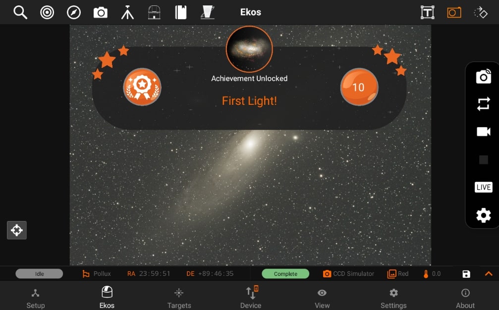
Capture ten sequences:
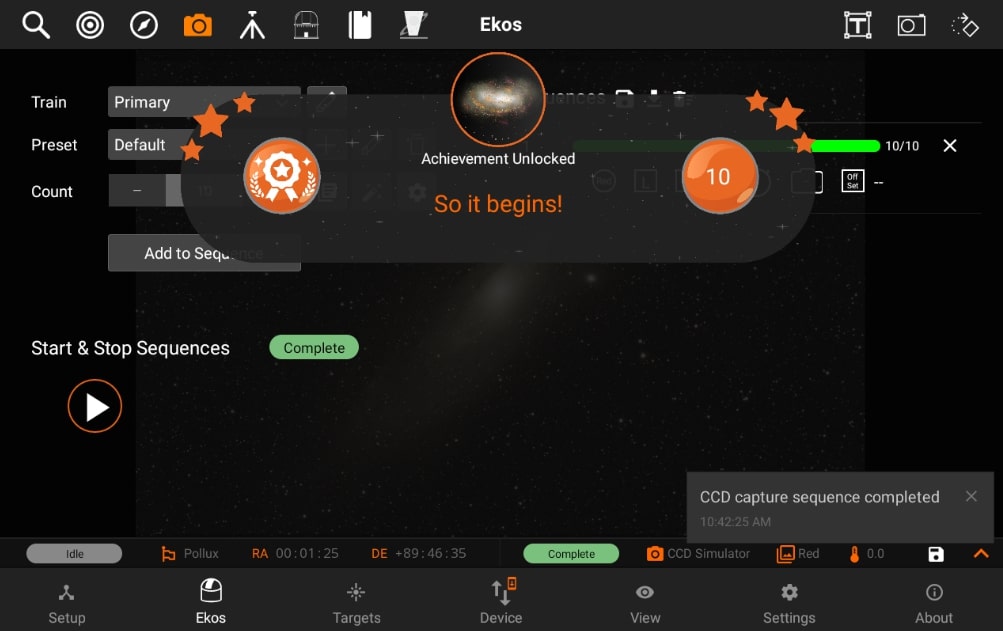
5.11.2. Push notifications
StellarMate App supports Pushover notifications to keep you informed of system events and alerts on your mobile device.
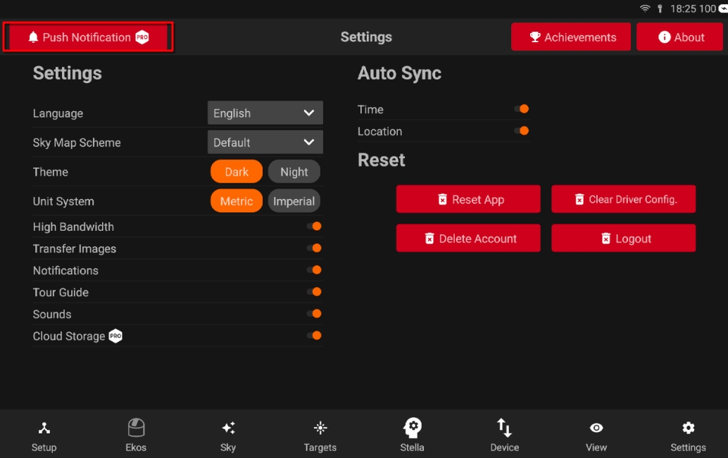
Setup Requirements - Download the Pushover application from Google Play Store or Apple App Store - Create a Pushover account and obtain your user key

Configuring Notifications - Paste your Pushover user key in the designated field - Tap Save to store your configuration
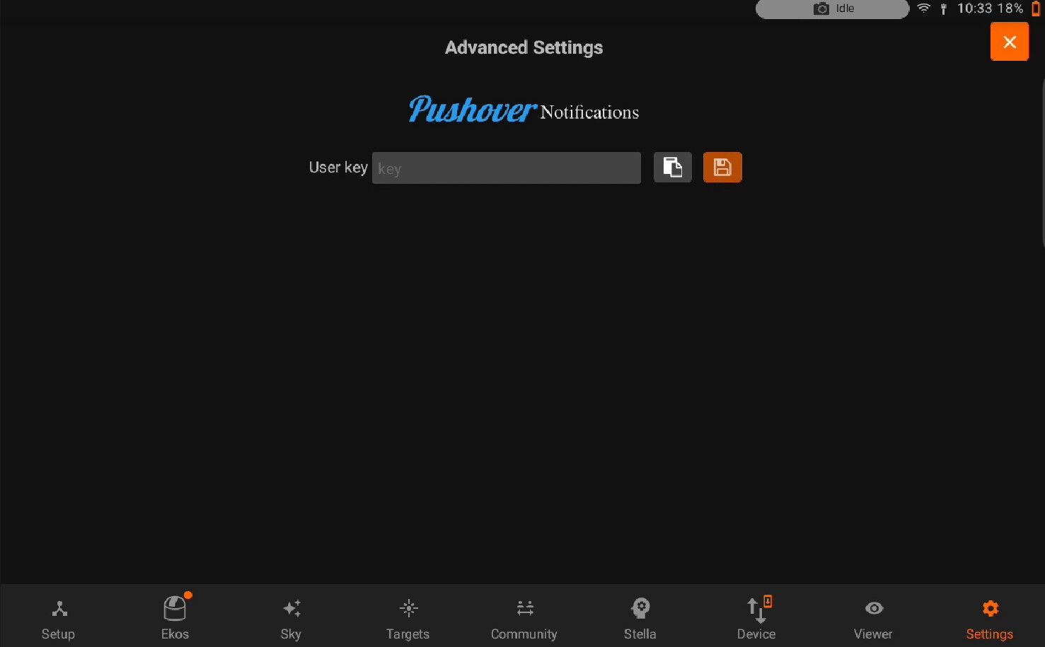
Adjust notification categories to select which events trigger alerts
Set severity levels to control notification priority and delivery method
Once configured, you will receive real-time notifications on your mobile device for selected StellarMate events and system alerts.